TM9-2330-368-14 & P
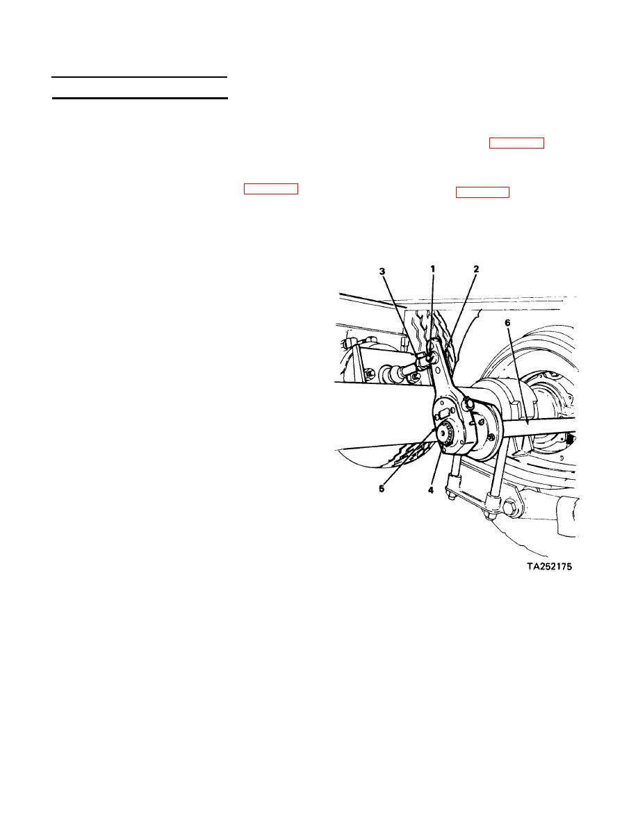
(d) Install cotter pin (1) in pin (2).
4-15. SERVICE BRAKES (cont)
( e ) Lubricate slack adjuster with grease-
d. Slack Adjusters.
GAA.
(1) Removal.
(f) Uncage air chambers (para. 2-27b).
(a) Chock wheels.
(g) Close air tank drain cocks.
(b) Cage air brake chamber (para. 2-27
(h) Adjust brakes (para. 4-15c).
a).
(c) Drain air tanks.
(d) Remove cotter pin (1) and headed
pin (2) from rod end (3).
(e) Remove lock ring (4) with lock
ring pliers. Remove slack adjuster
(5) from camshaft (6). Pull slack
adjuster arm away from push rod
end to clear. Use soft-faced hammer
to tap slack adjuster off if necessary.
(2) Installation.
(a) Install slack adjuster (5) on cam-
shaft (6). Turn camshaft to aline
slack adjuster with push rod end.
Use soft-faced hammer to tap in
place if necessary.
NOTE
The center hole of the three
holes on the slack adjuster
must be alined with push rod
end. If it is not, reinstall slack
adjuster.
(b) Install lock ring (4) on camshaft (6)
using lock ring pliers.
(c) Install headed pin (2) through cen-
ter hole of slack adjuster (5) and
push rod end (3).
4-28

