TM9-2330-368-14 & P
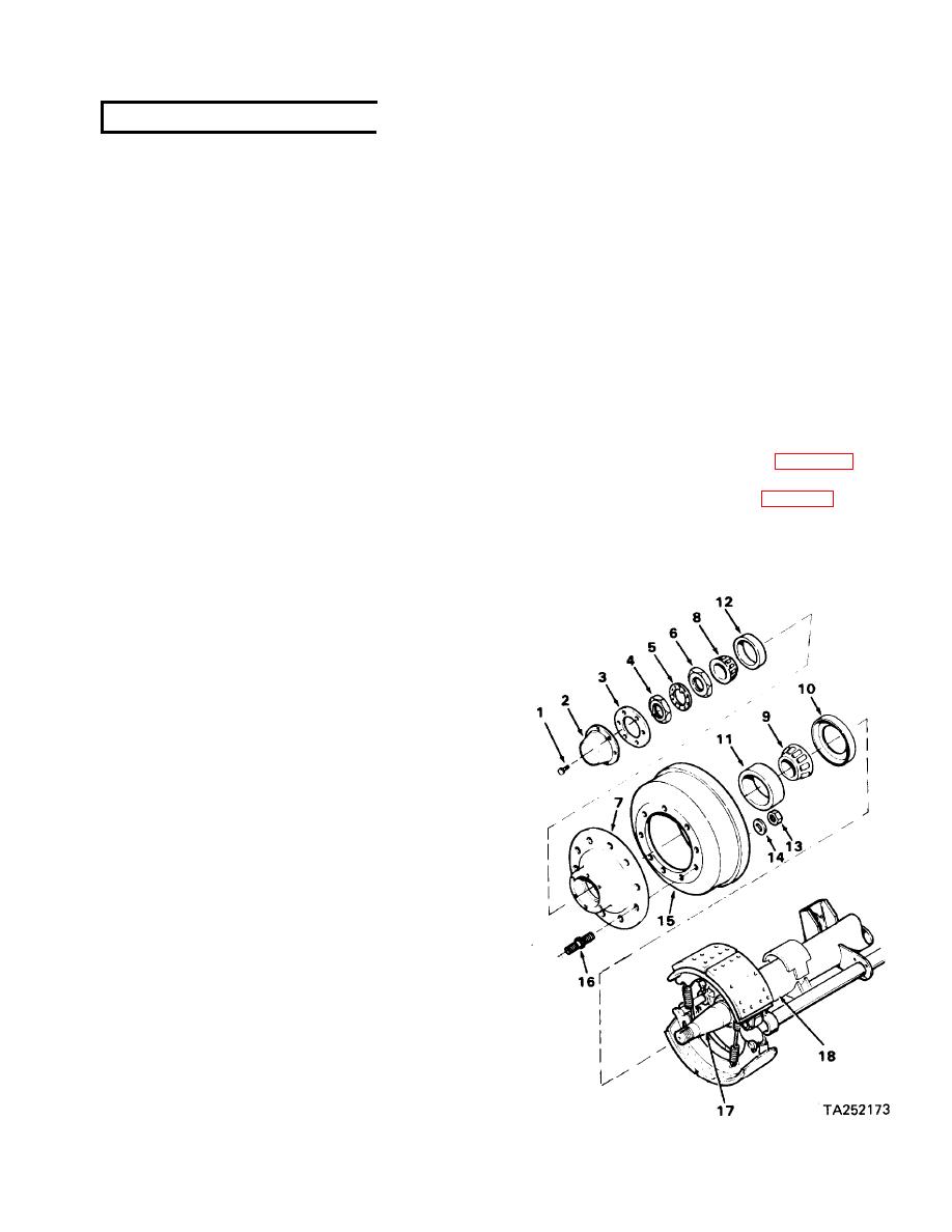
(9) Install inner spindle nut (6) on spindle
4-14. HUBS AND DRUMS (cont)
(17) and tighten nut against bearing
while turning brake drum (15) by hand.
(2) Inspect brake drum visually for deep
When there is a slight bind, back off in-
scoring, excessive wear (ridge) and
ner spindle nut 1/3 turn to allow free
other irregularities. Report condition
rotation of wheel.
to direct support maintenance.
(10) Install spindle lock (5) and outer spin-
(3) Inspect hub cap, nuts, lock and hub
dle nut (4). Tighten outer spindle nut
for cracks and other damage.
to 250-400 lb-ft.
(4) Inspect spindle for damaged threads,
(11) Repack hub cap (2) with grease GAA.
evidence of seizure and rough surfaces.
Report condition to direct support
(12) Install hub cap (2) and new gasket (3)
maintenance.
with six hex bolts (1).
d. Repair. Replace gasket, seal and all defec-
(13) Rotate brake drum (15) to assure free
tive parts,
movement without binding.
e. Installation.
(14) Uncage air brake chamber (para. 2-27 b).
(1) Install studs (16) in hub (7) if removed.
(15) Install wheels and tires (para. 3-6).
(2) Install inner bearing cup (11) in hub (7),
with narrow edge outward. Seat with
steel drift.
(3) Pack inner bearing cone (9) with grease
GAA and install in cup.
(4) To assure proper fit, place seal (10) on
spindle up to first rubber rib. The cor-
rect seal will not go on any further due
to designed interference.
(5) Place seal (10) on rear of hub (7) with
the words "OIL SIDE" facing inward.
Make sure that seal is straight. Using a
hammer and piece of flat hardwood,
tap the seal into hub until seal bottoms
out.
(6) Install outer bearing cup (12) in hub
(7). Pack hub cavity with grease GAA
up to level of inside diameter of outer
bearing cup (12).
(7) Install drum (15) on hub (7) with
back nuts (13) and washers ( 14) if re-
moved. Tighten nuts (13) to 300-330
lb-ft.
(8) Pack outer bearing cone (8) with grease
GAA and install in Cup (12).
NOTE
Be sure there is no brake drag be-
tween brake shoes and drum.
4-23

