TM 9-2590-206-14&P
(3) Connect electrical lead to lamp assembly.
b. Installation (Fig 4-29).
(4) Connect battery cables, and close turret
platform access door TM 9-2350215-20 (M60, M60A1),
(1) Align circuit breaker on mounting bracket,
TM 9-2350-257-20-1 (M60A1 RISE), or TM 9-2350-253-
and secure with two screws, nuts, and lockwashers.
20-1 (M60A3).
(2) Connect electrical connectors to circuit
(5) Place MASTER BATTERY switch in ON
breaker.
position, and check that HYDRAULIC PUMP lamp
illuminates.
(3) Connect battery cables and close turret
platform access door. See TM 92350-215-20 (M60,
M60A1), TM 9-2350-25720-1 (M60A1 RISE), or TM 9-
2350-253-20-1 (M60A3).
4-93.
Hydraulic Pump Control Panel Bracket.
a. Removal (Fig 4-29).
(1) -Remove HYDRAULIC PUMP electrical
switch (para 4-90).
(2) Remove HYDRAULIC PUMP indicator
lamp assembly (para 4-91).
(3) Remove
HYDRAULIC
PUMP
circuit
breaker (para 4-92).
(4) Disconnect
wiring
harness
cable
connector from receptacle on rear of gage indicator
panel (M60A1, M60A1 RISE and M60A3 only).
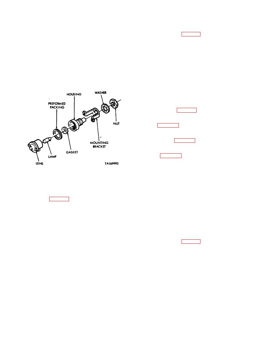
Figure 4-30. Repair of lamp assembly.
(5) Remove four screws and lockwashers
4-92.
Hydraulic Pump Circuit Breaker.
securing gage indicator panel support bracket and
hydraulic control panel bracket to mounting bracket, and
a. Removal (Fig 4-29).
remove gage indicator panel support bracket and
hydraulic pump bracket (M60A1, M60A1 RISE and
(1) Place
MASTER .
BATTERY switch in
M60A3 only).
OFF position.
(6) Remove two screws, nuts, and four
(2) Open turret platform access door, and
washers securing hydraulic pump control panel bracket
disconnect battery cables. See TM 9-2350-215-20 (M60,
to master control panel, and remove bracket (M60 only).
M60A1), TM 9-2350257-20-1 (M60A1 RISE), or TM 9-
2350-25320-1 (M60A3).
b. Installation (Fig 4-29).
(3) Disconnect lead assembly connectors
(1) Align hydraulic pump control panel bracket
from circuit breaker.
on MASTER CONTROL panel, and secure with two
screws, nuts, and four washers (M60 only).
(4) Remove
two
screws,
nuts,
and
lockwashers securing circuit breaker
to bracket.
Remove circuit breaker from bracket.
4-61


