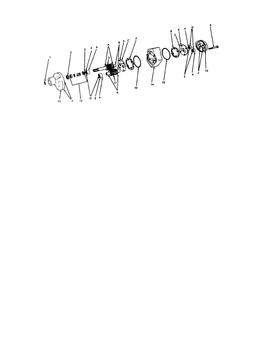
LEGEND
1. - RING
9. - BOLT
2. - SEAT
10. - PACKING PREFORMED
3. - RING RETAINING
11. - GEAR SPUR
4. - BEARING BALL ANNULAR
12. - SEAT PLAIN
5. - GEAR
13. - COVER, FRONT
6. - WEAR PLATE
14. - HOUSING
7. - GASKET
15. - COVER, END
8. - GASKET
AT 19706
Figure 4-9. Disassembly or assembly of hydraulic pump assembly.
(8) Position the drive gear (11) so that it will
(4) Install the remaining bearing (4) on the
mate with the drive gear (5) in accordance with dye
drive gear shaft
marks made during disassembly and insert the drive
(5) Install the retaining ring (3) securing the
gear into its bore in the end cover.
bearing on the drive gear draft.
(9) Place packing (10) on the machined
(6) Install the plain seat (12) and oil seal seat
surface of the end cover (15).
(2l on the drive gear assembly with the tapped surface
(10) Lower housing (14) into the end cover,
of the seat facing up.
position it in accordance with punch marks ma during
(7) Turn the end cover (15) with the small
disassembly. Locate housing over the dowel pins in the
opening down and install drive gear shaft (5) into its
cover and seat firmly.
bore in the end cover, and secure with snap ring (1).
4-20


