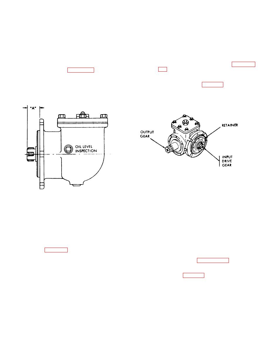
Maximum deviation from dimension "A" shall not
housing (71 and secure with six washers and screws 110
exceed + 0.0017.
and 91.
(3) Repeat procedures (1) and (2) as required
(12) Install plug (11) in fitting (12) and install
until dimension "A" and backlash specifications are
gasket (13) and fitting (12) in plate (14).
obtained.
4-34. Electromagnetic Clutch. The electromagnetic
Note. Refer to lubrication order (LO 9-2590-
clutch is mounted in the vehicle as an integral part of
213-120 for lubrication of right-angle drive power
the pump and drive assembly (pump. magnetic clutch,
take-off.
and right-angle drivel.
f. Adjustment. To adjust the right-angle drive
through 4-7 for instructions on removal and installation
power take-off, refer to figure 4-12 and proceed as
of the complete unit. Follow the alphabetical sequence
follows.
of views for removal and the numerical sequence of
(1) Lock the output drive shaft and rotate the
views for installation. Refer to figure 4-8 for disassembly
input drive shaft and check for backlash. Tighten or
and assembly of electromagnetic clutch from/to the
loosen the input drive shaft retainer until backlash
pump assembly and right-angle drive.
specification is obtained.
(2) Check measurement of dimension "A".
DIMENSION "A" - SUBTRACT MEASURED DIMENSION ON
HOUSING FROM SUM TOTAL DIMENSION ON
GEAR SET (MATCHED PAIR)
DIFFERENCE SHOULD
BE WITHIN *0.0017 AFTER BACKLASH IS SET.
BACKLASH
- 0.004 TO 0.006.
AT 19709
Figure 4-12. Adjustment dimensions for right-angle drive take-off.
b. Disassembly. For disassembly electromagnetic
(4) Remove key (7) from shaft (8).
(5) Disconnect retaining ring (10) from
clutch, refer to figure 4-13 and
shaft (8) and remove bearing (9).
proceed as follows.
(1) Disconnect retaining ring (4) from shaft (8)
and remove bearing (5).
instructions.
(2) Using spanner wrench 5120-293-0798,
d. Inspection. Check the components for wear
remove threaded ring (11) from clutch assembly (6).
limits as specified in table 4-11.
(3) Slide shaft (8) from clutch assembly (6).
4-25


