
FORM G2 MOTOR
SHAFT AND CENTRIFUGAL
EASY-SERVICE FEATURES
MECHANISM REPLACEMENT
1.
Relay and centrifugal switch points are pre-set at
the factory for proper operation and quick installation.
2.
Shaft de-burring is unnecessary to remove the
TO REMOVE SHAFT
rotor, thus reducing disassembly time. New 5/8-inch
diameter bearings and 1/2- or 5/8-inch shaft extensions
1.
Remove thrust washers and snap rings.
make replacement easier.
2.
Check and record the position of the rotor on the
3.
Machining of the bearing hub OD is not required
shaft.
to change the motor from a solid- to a resilient-cradle
3.
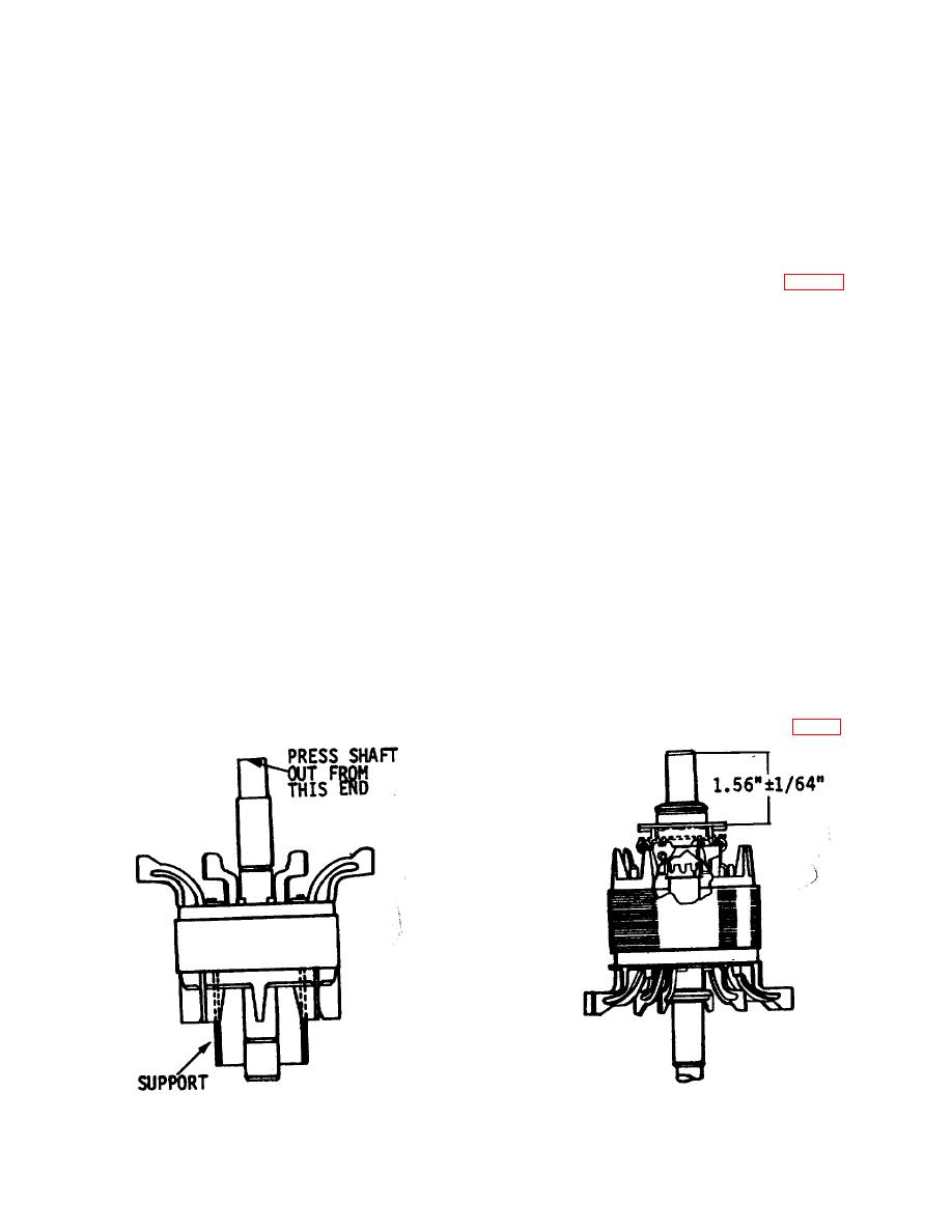
Support the rotor on the opposite-pulley end, on
base mounting.
a tube with square ends. Support should be as close as
4.
An easy-to-read connection indicator is imprinted
possible to the aluminum end ring (see Fig. 1). Press
on the outside of the terminal-box cover for ready
against the pulley end of shaft, at the step in the shaft if
reference.
possible.
5.
Leads of braidless neoprene material have a
clear color coding for motor lifetime. This simplifies lead
TO REASSEMBLE SHAFT
identification during hookup.
6.
A new thrust washer is simply constructed for
1.
Support the rotor in the same way as in removal
easy removal.
and press the shaft to the original or recorded position by
7.
Oilers alined on perimeter of motor shell simplify
pressing on the step between the extension and the
relubrication.
bearing diameter.
2.
Reassemble snap rings and thrust washers.
GENERAL DISASSEMBLY
TO REPLACE CENTRIFUGAL MECHANISM
1.
Remove the base if it is still on the motor.
2.
Take out through-bolts.
When the centrifugal mechanism is at standstill,
3.
Remove pulley-end end shield.
the push collar stops against the thrust washer snap ring.
4.
Pull rotor out the pulley end.
The backplate is held onto the shaft by pressing it over a
CAUTION: Use care in handling the rotor to prevent
serrated bushing, which is prevented from moving along
bending of fan blades.
the shaft by another snap ring.
5.
Notice how thrust washers are assembled to the
Remove snap rings from shaft with a plier No. 2
shaft. Three thicknesses of these washers are available
or with a plier No. P 102.
for endplay adjustment.
Assemble mechanism to shaft by pressing
6.
Take the other end shield off the stator.
against the end of the push collar, not on the face. Press
CAUTION:
Do not damage winding guards.
until the end of push collar is 1.56 inches (plus or minus
1/64 inch) from the switch end of shaft when the
mechanism is in the running position (see Fig. 2).
Fig. 2. Shaft rotor assembly with centrifugal mechanism
Fig. 1. Shaft rotor assembly
40
