
TM 9-4110-255-14
4-47. SOLENOID VALVE L2 (DEFROST LINE) TESTING AND REPAIR . - Continued
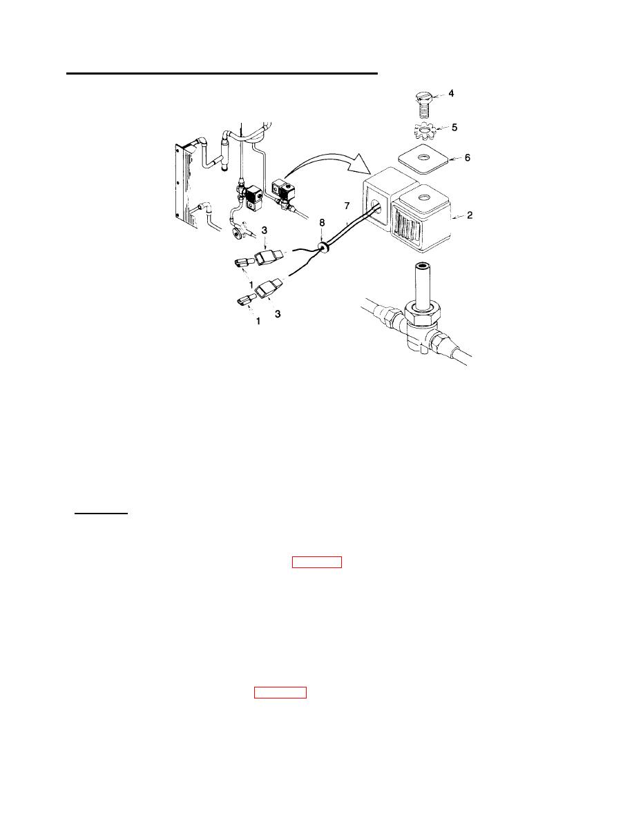
Figure 4-42. Solenoid Valve (Defrost Line)
NOTE
Mounting hardware is not supplied with coil. Screw and lock washer must be retained for use
during installation of coil.
(2) Remove screw (4), lock washer (5), data plate (6), and coil (2).
(3) Cut wire leads (7) if necessary and remove grommet (8).
c. Installation.
(1) Push wire leads (7) through grommet (8) and install grommet into coil (2).
(2) Install two tab housings (3) and tabs (1) (para 4-19).
(3) Install coil (2), data plate (6), lock washer (5), and screw (4).
(4) Using tags and wiring diagram (fig. 14), connect tabs (1). Remove tags.
NOTE
FOLLOW-ON MAINTENANCE:
Close right side condenser door.
Connect battery (para 4-35) and put unit back into service.
4-118
