
TM9-4120-370-14
TO35E9-229-1
4-55. EVAPORATOR FAN MOTOR RELAY (K8) - Continued.
(4) Remove the external 24 volts dc power source from coil terminals X1 and X2,
d.
Installation
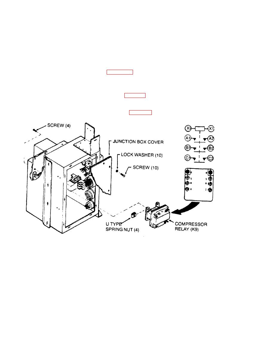
(1) Place U type spring nuts on four mounting holes.
(2) Using screwdriver, secure relay with four screws.
(3) See tags and wiring diagram (Figure 4-20) and connect wire leads.
(4) Remove tags.
(5) Using a screwdriver, secure junction box cover with ten screws and lock washers,
Followon procedure:
Install junction box (See para 4-45.)
Preliminary procedure:
Remove junction box. (See para 4-45,)
Figure 4-76. Compressor R e l a y
(k9)
a.
Removal
(1) Using a screwdriver, remove ten screws and lock washers from junction box cover.
( 2 ) Remove cover.
(3)
Tag and disconnect wire leads.
(4)
Using screwdriver, remove four screws from relay.
(5)
Remove U type spring nuts from relay.
(6)
Remove relay.
b. Inspection
(1) Check for loose, corroded, missing, or broken terminal connections.
