TM 9-4120-370-14
TO 35E9-229-1
4-52. CONTROL RELAY (K10) - Continued.
(3) Check that wire leads to socket are not damaged, loose, or missing and that they are properly connected.
(See wiring diagram, Figure 4-20.)
c. Test
(1) Using a multimeter set on high OHMS scale, check continuity.
Continuity should be indcated across the following contacts:
q
A to B
1 to 7
3 to 9
Continuity should not be indicated across the following contacts:
q
1 to 4
3 to 6
(2) If relay fails above tests, replace relay.
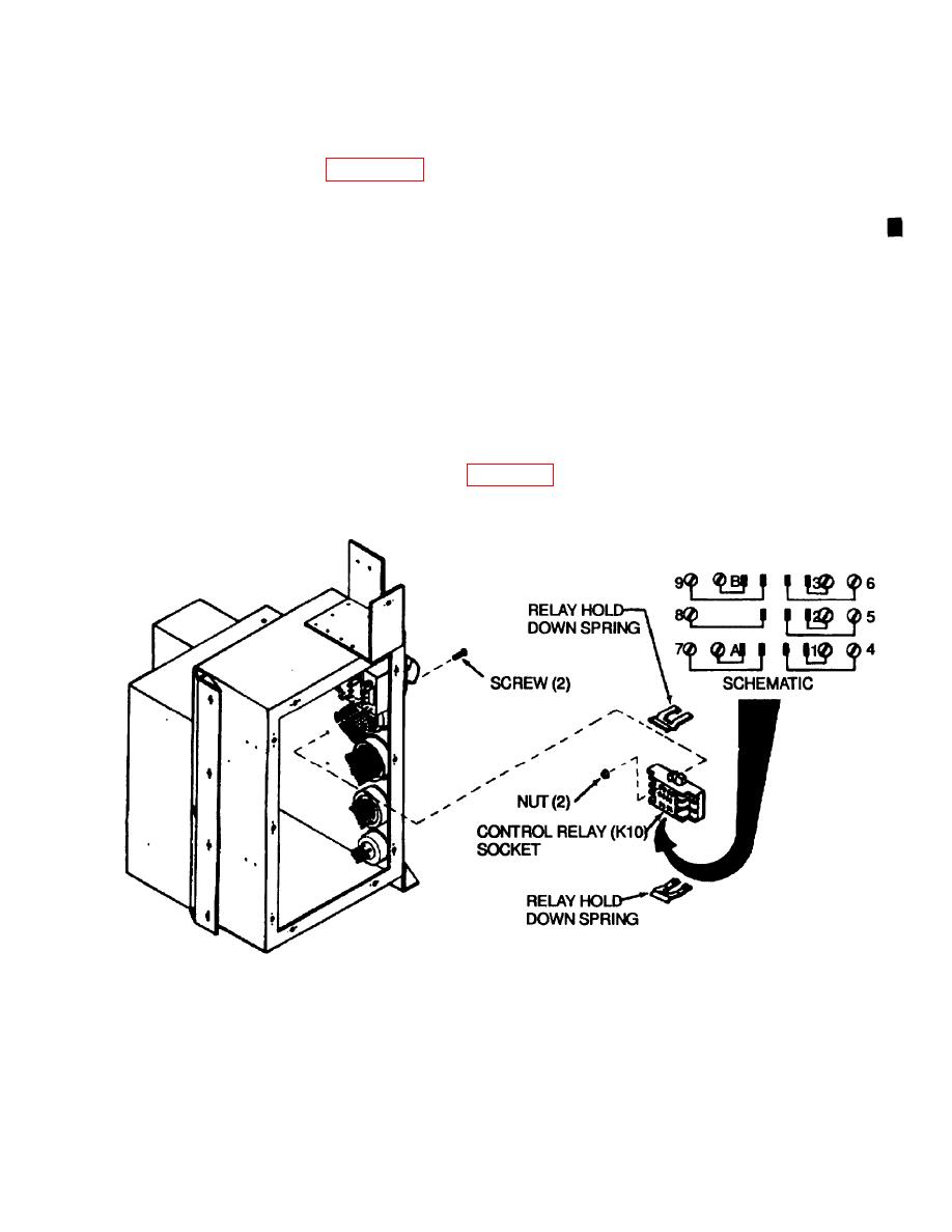
(3) Using a multimeter and schematic shown on Figure 4-72, check continuity between contacts and terminals
of control relay socket.
Figure 4-72. Control Relay (K10) Socket
d. Relay socket removal
(2) Tag and remove leads.
(3) Remove socket.
e.
Installation
Change 1
4-103

