
TM 9-4120-371-14
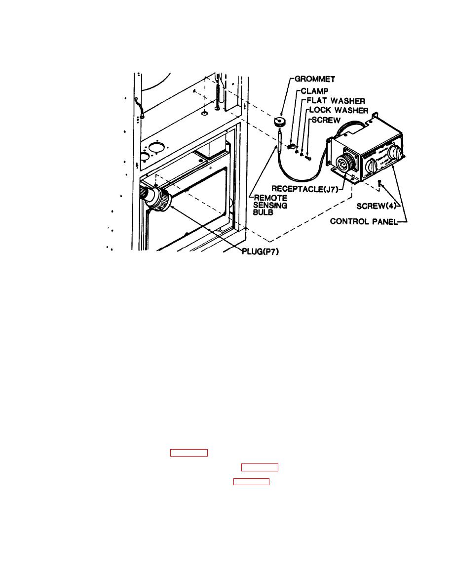
Disconnect plug (P7) from receptacle (J7).
(8)
Using screwdriver, loosen four captive panel fastener screws in junction box mounting flanges.
(9)
(10) Carefully slip junction box out far enough to gain acess to control panel mounting screws.
(11) Using screwdriver, remove four screws from control box.
(12) Remove grommet from bulkhead.
CAUTION
Take care that sensing bulb capillary line is not kinked and that bulb and capillary are not
cut or damaged during removal.
(13) Carefully slip remote sensing bulb down through bulkhead hole and remove control panel from unit.
b. Test/Replace/Repair. See the following paragraphs for individual component test, replacement, and
repair.
(1) Wiring harness. (See para 4-39.)
(2) Temperature control thermostat (S2). (See para 4-40.)
(3) Mode selector (rotary) switch (S1). (See para 4-41.)
