TM 9-4120-371-14
b. Inspection
(1) Check that mounting hardware, circuit breaker cover, actuator arm, and circuit breaker are in place
and secure.
(2) Check that wire leads are properly connected to circuit breaker and are not damaged. See wiring
diagram (fig. 4-23).
(3) Check circuit breaker for signs of overheating or other visible damage.
c. Test
(1) Set circuit breaker reset bar in OFF position.
(2) Use multimeter set on lowest OHMS scale to check continuity between terminals A1 and A2, B1
and B2, C1 and C2, and auxiliary switch terminals C and NO. All contacts should be open. If there is continuity
on any check, replace circuit breaker.
(3) Press reset bar toward the OFF stop, then place it in the ON position.
(4) Use a multimeter set on the lowest OHMS scale and repeat continuity checks between terminals A1
and A2, B1 and B2, C1 and C2, and auxiliary switch terminals C and NO. All four contacts should be closed. If
there is no continuity on any check, replace circuit breaker.
d. Removal
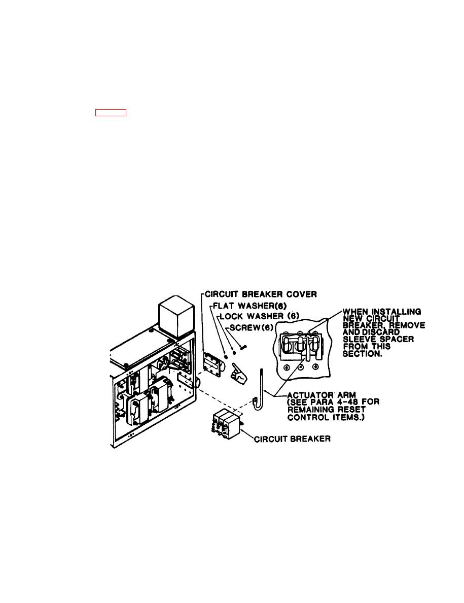
(2) Using screwdriver, remove six screws, lock washers, and flat washers.
(3) Using pliers, pull shaft that holds reset toggles together and disconnect reset actuator arm.
(4) Remove circuit breaker and circuit breaker cover.


