
TM 9-4120-385-14
Replace tie straps as necessary.
20.
Carefully place wiring harness in general location within the unit.
21.
Connect electrical leads to TB1. Refer
to Table 4-9 for correct connections.
22.
Connect electrical leads to TB2. Refer to Table 4-10 for correct connections.
23.
Connect leads to ground E2. Secure with screw, two flat washers, lockwasher,
24.
and nut.
Install J4 and J10 and secure with four screws and nuts each.
25.
Connect harness connectors P4 and P10.
26.
Connect electrical leads disconnected during repair procedures. Refer to Table
27.
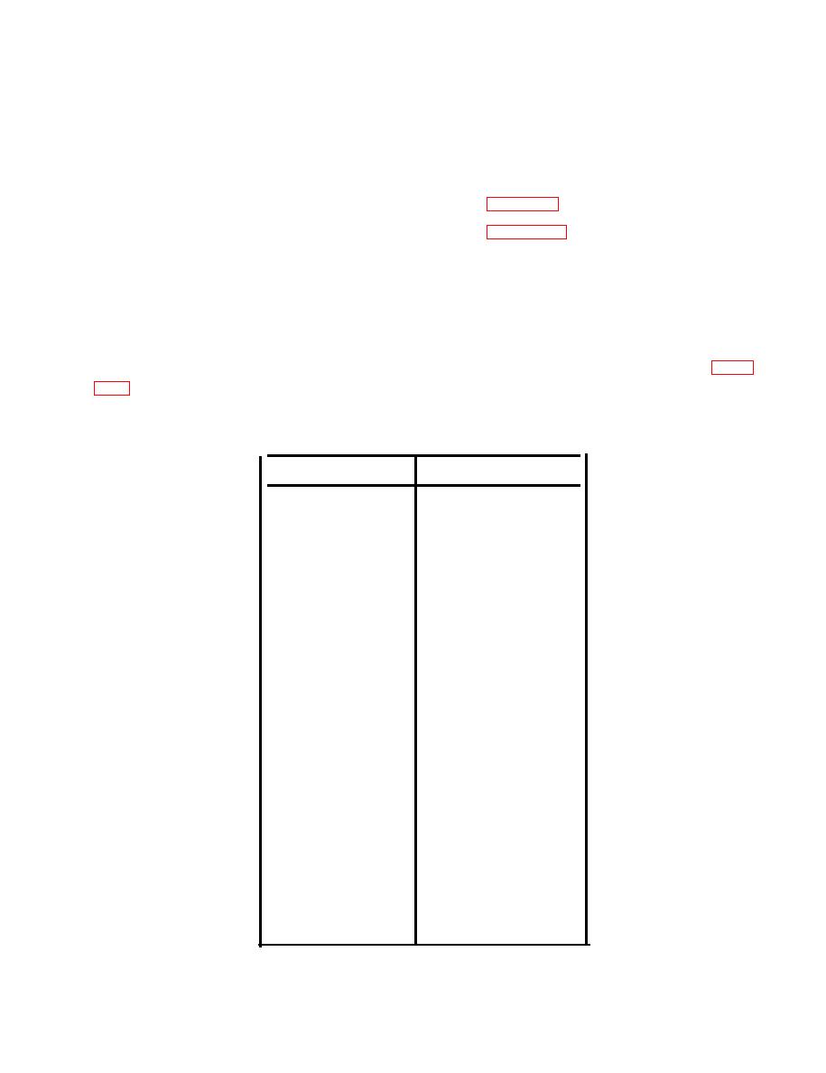
Table 4-11. JUNCTION BOX ELECTRICAL LEADS CONTINUITY CHECK
TO
FROM
K2-C1
TB11
CB-A1
TB11
TH2
TB12
TB1-3
TB12
TB1-4
CB-B1
TB1-2
CB-B2
CB-A2
K1A2
TH1
XF1-2
CR-1
TX1
CR-4
TX2
E3
E2
CB-NO
XF11
XF2-1
CR3
K6-1
TB1-6
K6-2
K6-1
K1B1
TB1-6
K1X2
K1B2
K1X2
K6-3
K2-X1
K1X1
TB1-8
K2-X1
TB17
TB1-8
CR-2
TB1-7
K9-2
TB2-6
K9-3
TB1-8
K9-5
TB1-7
K9-5
K6-5
K9-1
XF2-2
