
TM 9-4120-388-14
This task consists of:
a. Inspection
b. Test
c. Removal
d. Installation
INITIAL SET-UP:
Equipment Condition
Junction box cover removed (4-47).
Inspection.
a.
(1) Check for loose wire connections.
(2) Check for cracks, evidence of overheating, and other visible damage. Replace if damaged.
b.
Test.
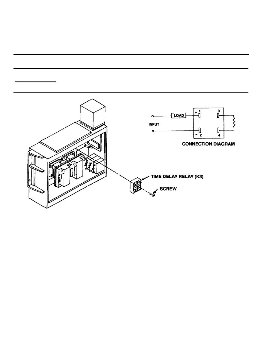
(1) Using a multimeter set on lowest OHMS scale, check continuity.
Terminal 1 (+) to 2 (-) - Continuity should not be indicated
Terminal 3 to 4 - Continuity should be indicated
(2) Set multimeter at appropriate DC voltage scale.
(3) Apply power across terminals 1 and 2. Voltage indicated should be 24 5 volts DC. After approximately 30
seconds time delay, voltages should drop to less than two volts.
(4) Replace time delay relay if it fails any of the above tests.
Removal.
c.
(1) Tag and remove wire leads.
(2) Remove screw from time delay relay.
(3) Remove time delay relay.
4-102
