
TM 9-4120-388-14
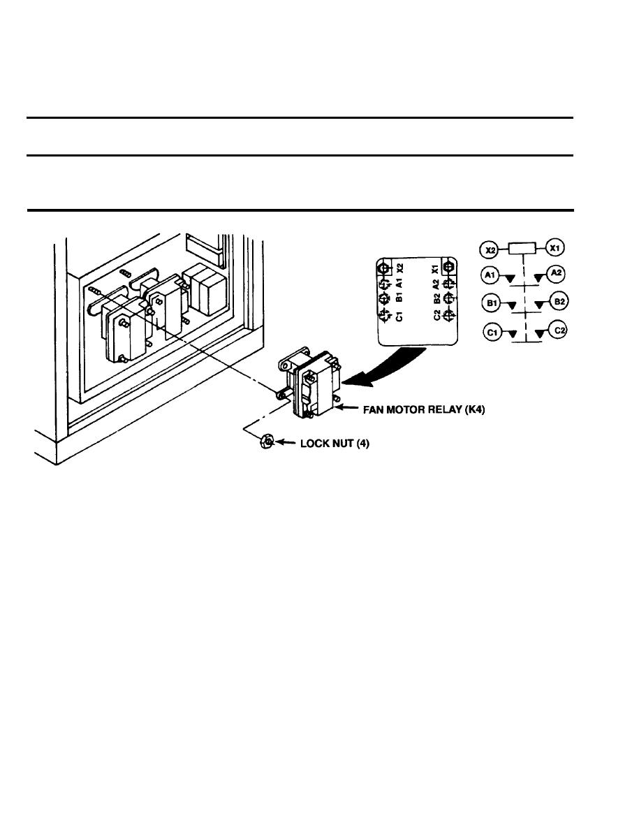
4-57. FAN MOTOR RELAY (K4).
b. Inspection
a. Removal
This task consists of:
d. Installation
c. Test
INITIAL SET-UP:
Equipment Condition
Junction box cover removed (4-47).
Removal.
a.
(1) Tag and disconnect wire leads.
(2) Remove four lock nuts from relay.
(3) Remove relay.
b. Inspection.
(1) Check for loose, corroded, missing, or broken terminal connections.
(2) Check relay for cracks, evidence of overheating, and other visible damage. Replace if damaged.
c.
Test.
(1) Use a continuity tester or a multimeter set on the lowest OHMS scale to check continuity between terminals
(A1 and A2, B1 and B2, and C1 and C2). All three contacts should be open. If there is continuity, replace
the relay.
(2) Check continuity between coil terminals (X1 and X2). If there is no continuity the coil is open. Replace the relay.
(3) Apply external 24 volts DC power source across terminals (X1 and X2) and repeat continuity checks be-
tween terminals (A1 and A2, B1 and B2, and C1 and C2). All three contacts should be closed. If there is
no continuity, replace the relay.
(4) Remove the external 24 volts DC power source from coil terminals (X1 and X2).
4-108
