
TM 9-4120-395-14&P
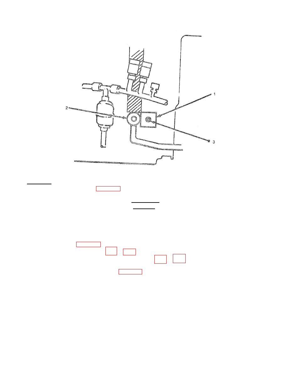
Figure 5-9. Reversing Valve
c.
Installation.
(1) Place the reversing valve (2, Figure 5-9) into the unit.
(2) Wrap wet rags around reversing valve (2) at connection points.
CAUTION
Direct flame away from tile reversing valve.
(3)
Purge system with nitrogen and braze the tubing joints. See paras 5-6 and 5-7.
(4)
Remove the wet rags.
(5)
Replace drier. See para 5-12.
(6)
(7)
(8)
Install the reversing valve solenoid (1) on the reversing valve (2) with the two screws (3).
(9)
Install both front door assemblies. See para 4-17.
5-35
