
TM 9-4120-395-14&P
(10)
Reinstall and tape in place tubing insulation that was removed. If it was damaged, replace with tubing
insulation.
(11)
(12)
Secure the control box (7) with the two screws (8).
(13)
Replace the cover on the control box and secure with two screws See para 4-23
(14)
Slide the dividing wall (5) down, replace filter brackets (6), and secure dividing wall with two screws (4).
(15)
Test the system per para 5-11. Then continue with step (16) below if system had a running burnout.
Otherwise go to step (19).
NOTE
If the system has suffered rotating burnout, it is advisable that the oil of the replacement
compressor be tested and judged acid free before the system is considered satisfactorily
cleaned.
(16)
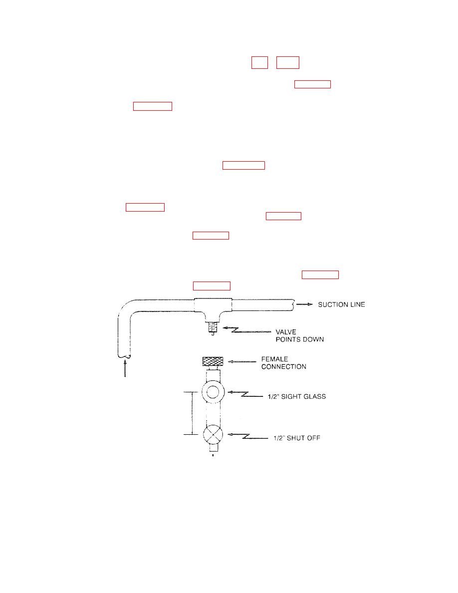
Make pressure drop check across the drier. See Figure 5-11. When the trapped oil level appears in the sight
glass (less than an ounce is needed), the oil may be slowly transferred to the beaker of the acid test kit.
NOTE
Where a severe running burnout has occurred, an Increased pressure drop will be measured.
(17)
Change driers per para 5-12 whenever pressure drop approaches or exceeds that allowed for temporary
operation during cleanup or acid reading is above 0.05. See Table 5-4.
(18)
Keep changing both the driers until the pressure drop stabilizes at a figure equal to or below that permitted for
permanent operation in a system. See Table 5-3.
NOTE
At this point, it is the technician's option to leave the second drier in the system or remove it
from operation. If the system is to be opened to permit the permanent removal of the second
drier, then the remaining, drier should be changed once more. See para 5-12.
(19)
Install both front door assemblies. See para 4-17.
Figure 5-11. Oil Trap Valve Connection For Oil Samples
5-39
