
TM 9-4120-402-14
4-5.
INSTALLATION INSTRUCTIONS. - continued
(b) If the alternate connector location to be used is on either side of the unit, determine which side
best suits your installation and proceed as follows:
1
Remove lower front cover panel from air conditioner. (See paragraph 4-20.)
2
Remove conditioned air intake grille and filter. (See paragraph 4-23.)
3
Remove control assembly. (See paragraph 4-34.)
4
Remove connector J4, hardware, and gasket from control assembly. (See paragraph 4-
35.)
5
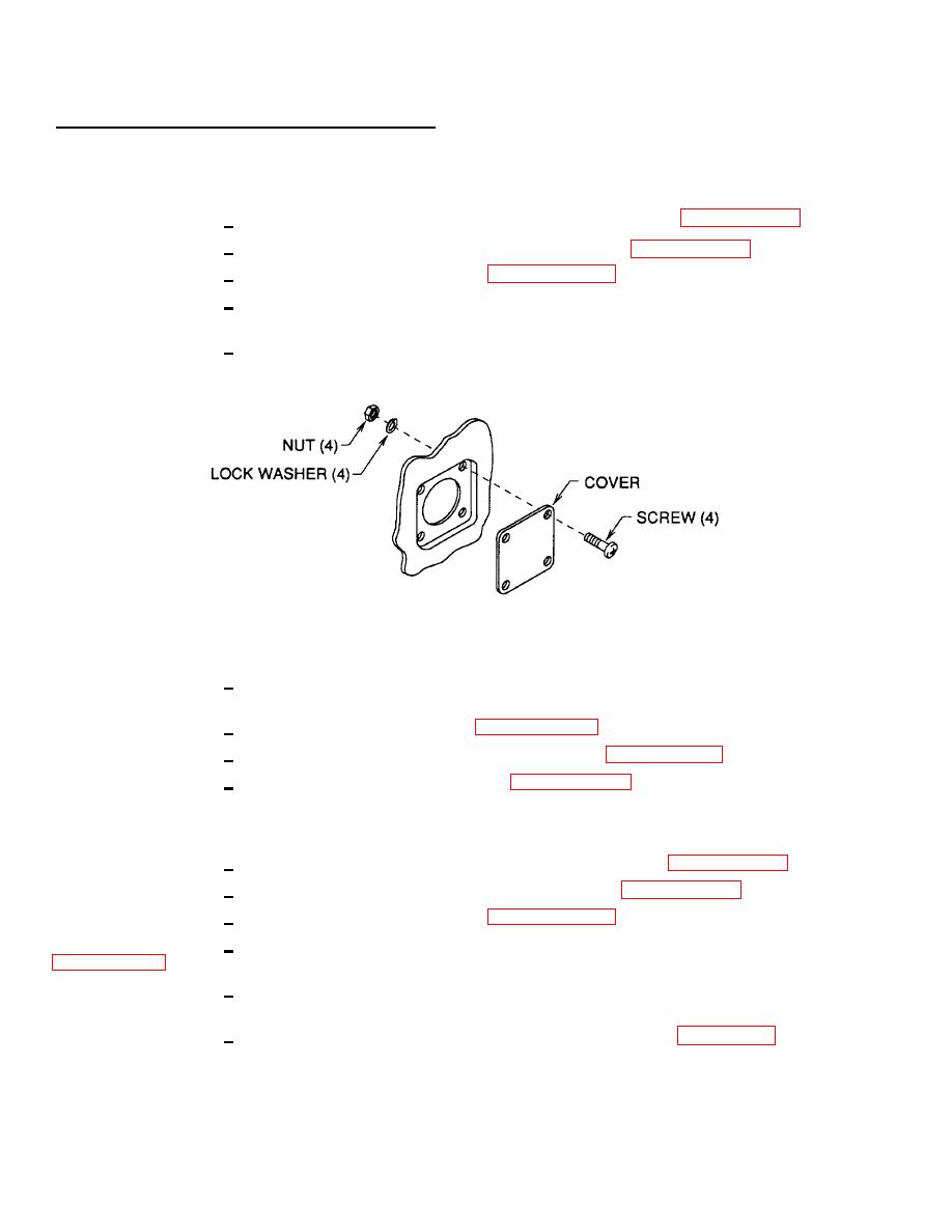
Remove cover plate and hardware from alternate location and reinstall on control
assembly.
Figure 4-4. Cover Plate Removal/lnstallation
6
Install connector J4 in alternate location using hardware and gasket removed in step 4
above.
7
Install control assembly. (See paragraph 4-34.)
8
Install conditioned air intake filter and grille. (See paragraph 4-23.)
9
Install lower front cover panel. (See paragraph 4-20.)
(c)
If the alternate connector location to be used is on the rear side of the unit, proceed as follows:
1
Remove lower front cover panel from air conditioner. (See paragraph 4-20.)
2
Remove conditioned air intake grille and filter. (See paragraph 4-23.)
3
Remove control assembly. (See paragraph 4-34.)
4
Remove connector J4, hardware, and gasket from control enclosure assembly.
(See
5
Remove cover plate and hardware from alternate location and reinstall on control
enclosure assembly.
6
Fabricate new, extended wiring harness. (See appendix F, figure F-48.) Run braided wire
bundle through back of control enclosure assembly and out slotted hole in top prior to soldering connector J4 to wires.
Connectors from short (existing) harness can be used if in good condition.
4-13
