TM 9-4120-411-14
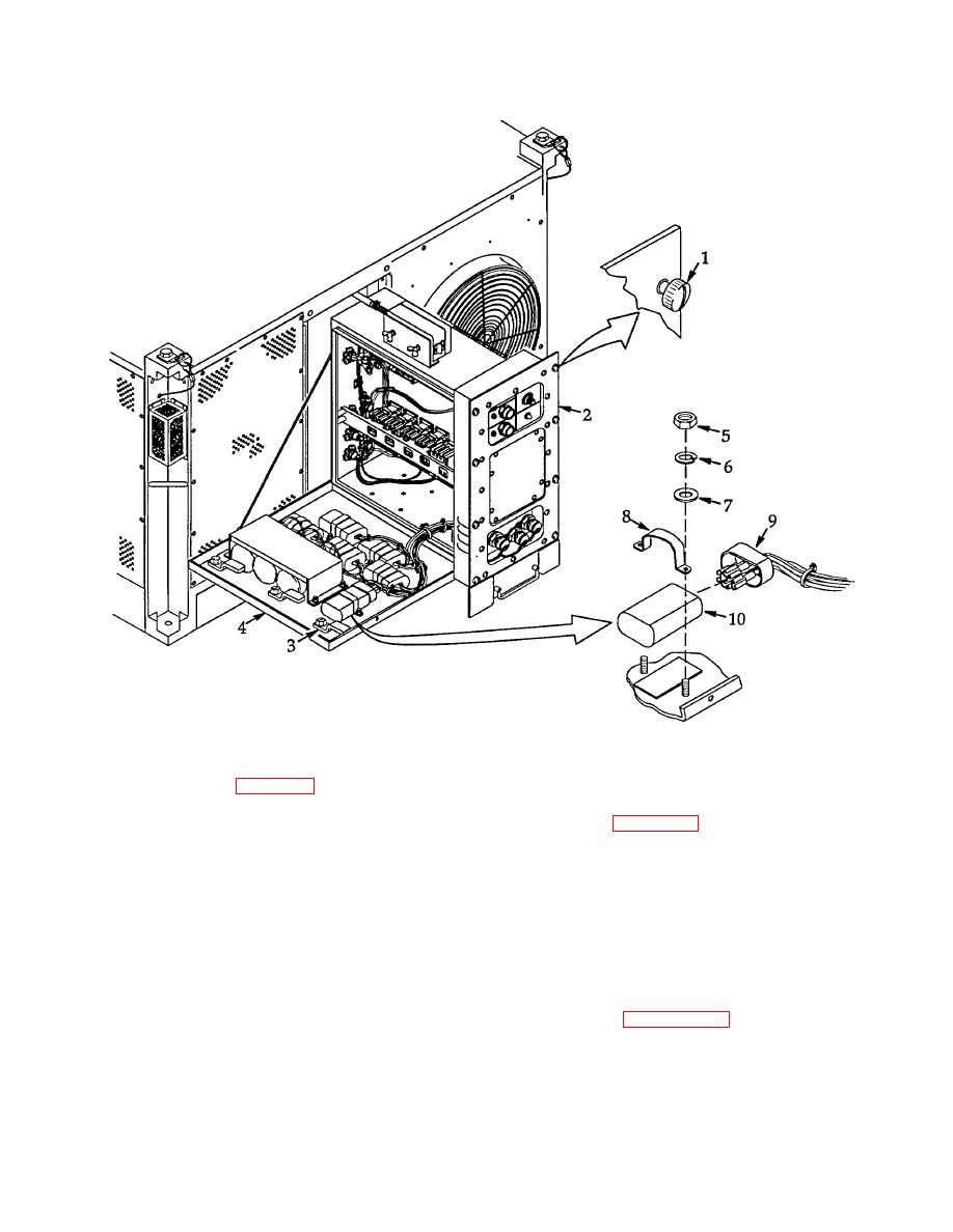
Figure 4-28. Capacitors (C1 thru C6).
b. Installation. See figure 4-28.
(1) Connect wire leads to capacitor (10) per tags and wiring diagram figure 4-14. Remove tags then carefully
place cap (9) over terminals.
(2) Place capacitor (10) in position with bracket (8) over it on mounting studs. Secure bracket with two flat
washers (7), new lock washers (6), and nuts (5).
(3) Close power box as sembly cover (4) and turn three latches (3) to secure.
(4) Carefully slide electrical assembly (2) into frame. Be sure no cables or wires are pinched. Secure with
eight captive screws (1).
(5) Connect FDECU main power cable to power source and operat e per paragraph 2.4.
4-75

