TM 9-4120-411-14
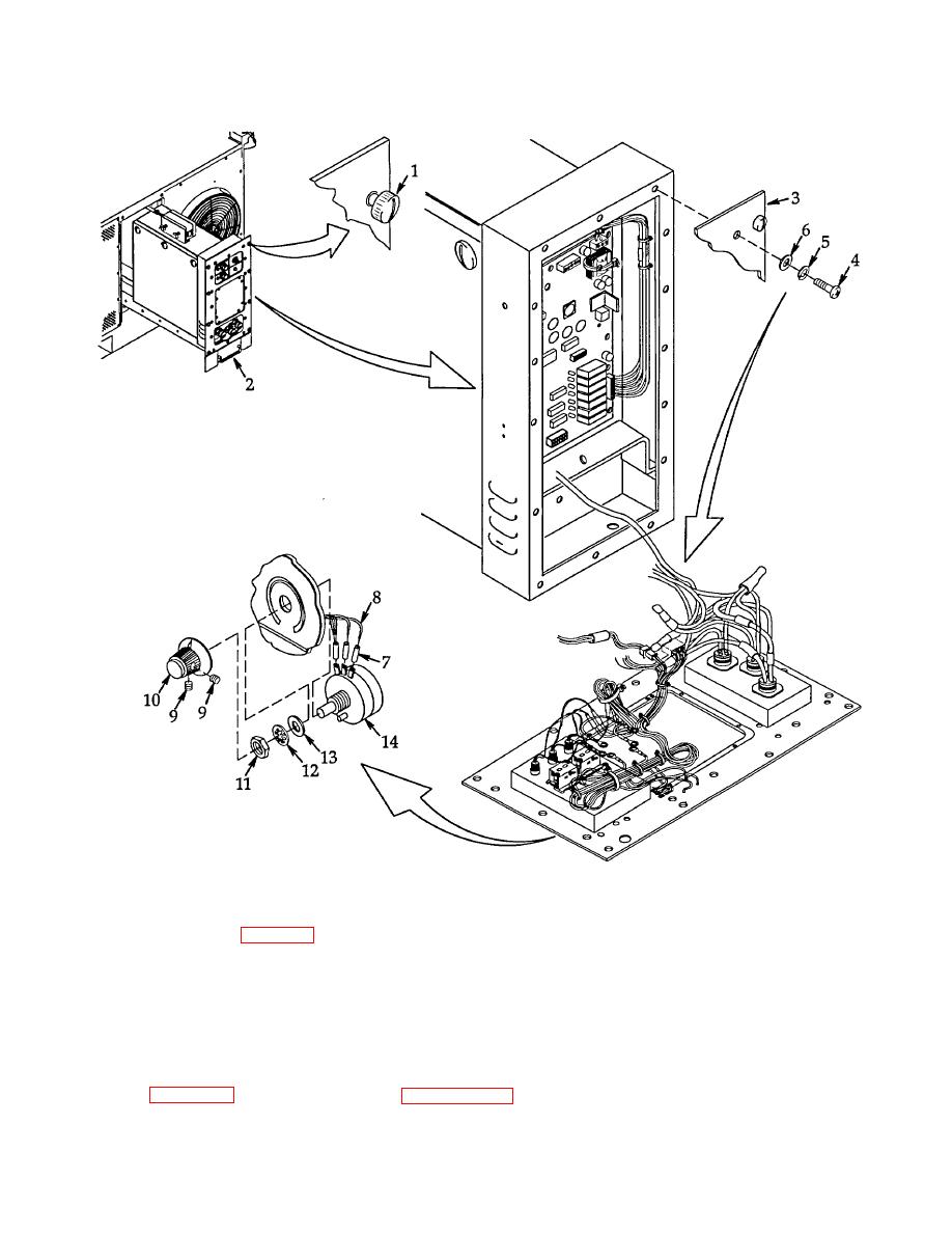
Figure 4-41. Potentiometer (R2).
b. Installation. See figure 4-41.
(1) Install potentiometer (14) and align anti-rotation pin. Secure using flat washer (13), lock washer (12), and
nut (11).
(2) Rotate potentiometer (14) shaft to position it at mid-point then install knob (10) with pointer at mid-point and
secure by tightening two set screws (9).
(3) Slide one piece of insulation sleeving (7) over each lead (8). Connect leads using tags and wiring diagram
figure 4-14. Solder connections per paragraph 4.16 then slide insulation sleeving over each connection and
heat to shrink in place using heat gun. Remove tags.
4-103

