TM 9-4910-387-14-2
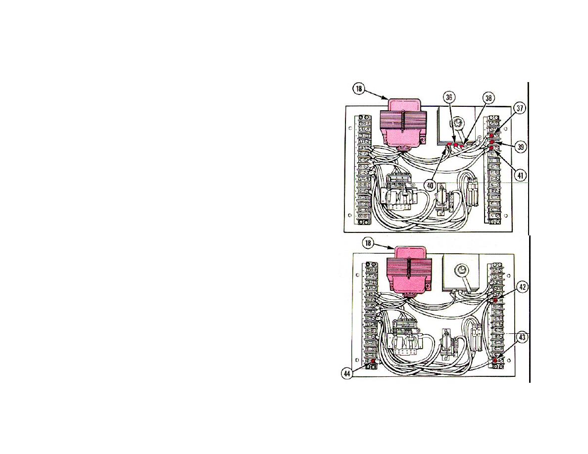
position other end with terminal lug on terminal D3.
26 SCREW (37). Install through terminal lug into terminal D3.
position other end with terminal lug on terminal D4.
28 SCREW (39). Install through terminal lug into terminal D4.
position other end with terminal lug on terminal D5.
30 WIRE WITH TERMINAL LUG TAGGED X2 FROM CONTROL
TRANSFORMER (18). Position on terminal D5.
31 SCREW (41). Install through two terminal lugs into terminal D5.
32 WIRE WITH TERMINAL LUG TAGGED H4 FROM CONTROL
TRANSFORMER (18). Position on terminal D6.
33 WIRE WITH TWO TERMINAL LUGS. Position one end on terminal
D6 and other end on terminal D16.
34 SCREW (42). Install through two terminal lugs into terminal D6.
35 WIRE WITH TWO TERMINAL LUGS. Position one end on terminal
D16 and other end on terminal C16.
36 SCREW (43). Install through two terminal lugs into terminal D16.
37 SCREW (44). Install through terminal lug into terminal C16.
6-205

