TM 9-4910-387-14-2
6-5. RH CONTROL EQUIPMENT ASSEMBLY-MAINTENANCE INSTRUCTIONS (cont) I
REASSEMBLY OF RH CONTROL PANEL ASSEMBLY (cont)
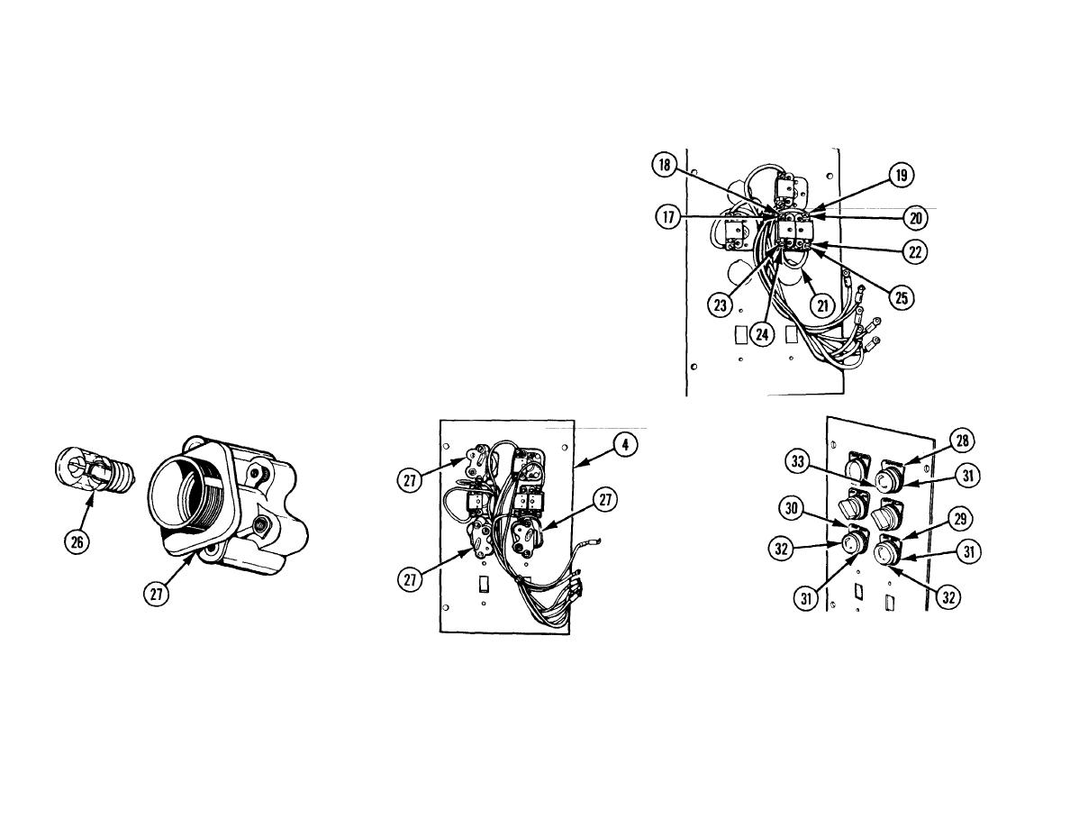
7 WIRE TAGGED C8. Position one end on 500-1000-OFF switch
contact (17), install screw (18) and tighten.
8 WIRE TAGGED C7. Position one end on 500-1000-OFF switch
contact (19), install screw (20) and tighten.
9 JUMPER WIRE (21). Position one end on 500-1000-OFF switch
contact (22) and other end to 500-1000-OFF switch contact (23).
10 WIRE TAGGED C9. Position one end on 500-1000-OFF switch
contact (23), install two screws (24 and 25) and tighten.
11 THREE CLEAR LAMPS (26). Install
13 THREE LEGEND PLATES (28, 29,
into three indicator lights (27) for
AND 30), THREE LENS CAPS (31),
12 THREE INDICATOR LIGHTS
(27).
COUNTING light, LUBE HEAT light,
TWO CLEAR LENSES (32), AND
Install in RH control panel (4).
and FUEL HEAT light.
AMBER LENS (33). Install
6-212

