
TM 9-4910-387-14-2
6-5. RH CONTROL EQUIPMENT ASSEMBLY-MAINTENANCE INSTRUCTIONS (cont) |
REASSEMBLY OF RH CONTROL PANEL ASSEMBLY (cont)
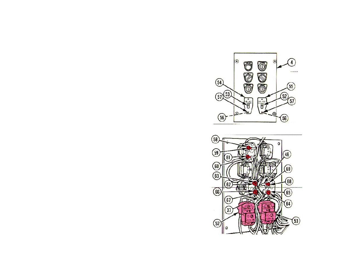
24 FUEL HEAT SWITCH (52) AND LUBE HEAT SWITCH (53).
Position on RH control panel (4), install two legend plates (54 and
55), four lockwashers (56), and four screws (57).
25 WIRE TAGGED C11. Position one end with terminal lug on
COUNTING light indicator contact (58), install screw (59) and
tighten.
26 WIRE TAGGED C14. Position one end with terminal lug on
COUNTING light indicator contact (60), install screw (61) and
tighten.
27 WIRE TAGGED Y. Position one end with terminal lug on FUEL
HEAT indicator light contact (62), install screw (63) and tighten.
28 WIRE TAGGED Y. Position one end with terminal lug on LUBE
HEAT indicator light contact (64), install screw (65) and tighten.
29 JUMPER WIRE (37) FROM FUEL HEAT SWITCH (52). Position on
FUEL HEAT indicator light contact (66), install screw (67) and
tighten.
30 JUMPER WIRE (46) FROM LUBE HEAT SWITCH (53). Position on
LUBE HEAT indicator light contact (68), install screw (69) and
tighten.
6-214
