TM 9-4910-387-14-2
6-5. RH CONTROL EQUIPMENT ASSEMBLY-MAINTENANCE INSTRUCTIONS (cont)
INSTALLATION (cont)
NOTE
Flush motor base with wires from FUEL HEAT switch must be installed
on top.
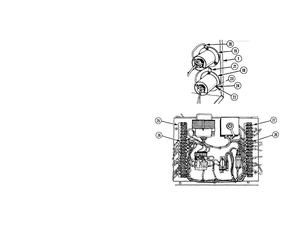
11 TWO FLUSH MOTOR BASES (19).
Position on RH enclosure
assembly (1).
12 TWO GROUND WIRES (20 AND 21) WITH ONE TERMINAL LUG
EACH, SIX SCREWS (22), SIX LOCKWASHERS (23), AND SIX
NUTS (24). Install.
NOTE
Wires to be connected to terminal strip C and terminal
strip D were tagged with termination points at
disassembly. Ensure that wires are connected to
correct locations.
13 THIRTEEN WIRES. Position on the LH terminals of terminal strip C
(25) as marked and secure with ten screws (26).
14 NINE WIRES. Position on RH terminals of terminal strip D (27) as
marked and secure with nine screws (26).
6-218

