TM 9-4910-387-14-2
6-6-. LH CONTROL EQUIPMENT ASSEMBLY-MAINTENANCE INSTRUCTIONS (cont)
REASSEMBLY OF LH CONTROL PANEL ASSEMBLY
NOTE
Wires were tagged with termination points at
disassembly. Ensure that wires are connected to
correct locations.
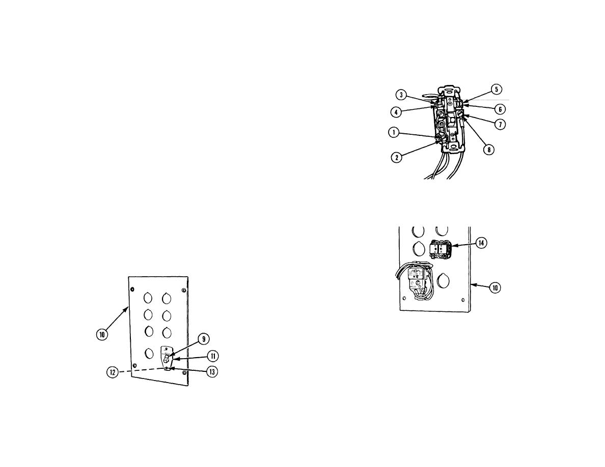
1 WIRE TAGGED B10. Position one end with terminal lug on
AUXILIARY MOTOR switch contact (1), install screw (2) and tighten.
2 WIRE TAGGED B8. Position one end with terminal lug on
AUXILIARY MOTOR switch contact (3), install screw (4) and tighten.
3 WIRE TAGGED B7. Position one end with terminal lug on
AUXILIARY MOTOR switch contact (5), install screw (6) and tighten.
4 WIRE TAGGED B11. Position one end with terminal lug on
AUXILIARY MOTOR switch contact (7), install screw (8) and tighten.
5 AUXILIARY MOTOR SWITCH (9). Position on LH control panel
(10).
MACHINE SCREWS (13). Install.
7 FORWARD-OFF-REVERSE SWITCH (14). Position on LH control
panel (10).
6-242

