
slightly to the right or left as required for
smoothest operation.
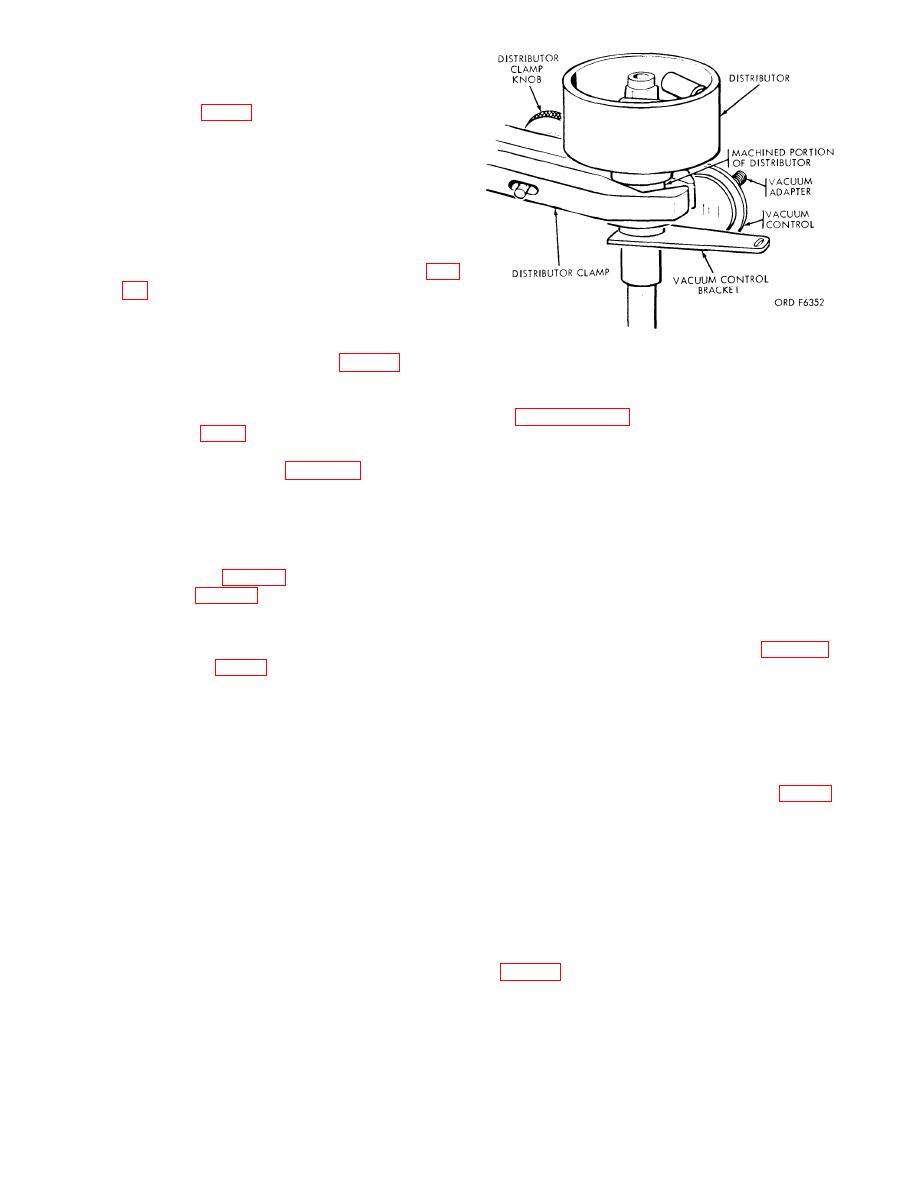
c. Mounting Governor Controlled Dis-
tributors (fig. 5) (with or without Vacuum
C o n t r o l l e d Breaker Plate). Clamp the
machined section of the distributor in the
distributor clamp (26) and turn the eleva-
tion handwheel (5) counterclockwise until
the distributor gear will engage the rubber
jaws of the chuck (11). See paragraph a
above for general mounting instructions.
If the distributor has a vacuum control,
install the correct vacuum adapter (fig.
vacuum hose (14) to the adapter.
d. Mounting Vacuum Controlled Distrib-
utors Requiring Special Sleeves. C l a m p
Figure 5. Mounting vacuum controlled distributors.
the proper sleeve bushing (fig. 12) in the
chuck (if Chevrolet sleeve bushing is being
used, be sure the clamping nut is up). In-
a. Mount the distributor as prescribed
sert the distributor shaft in the distributor
b. Set the motor and directional switch
clamp (26, fig. 3) so that the machined per-
tion of the distributor is in the distributor
(17) for the proper rotation of the distrib-
clamp as shown in figure 5. Secure the
utor to be tested, snap the speed range
distributor with the clamp locking knob.
selector (18) to 0-500 rpm position, and
Lower the mounted distributor with the
turn the speed control handwheel (15) until
elevation handwheel until the distributor
t h e tachometer indicator (3) registers
g e a r or shaft engages the chuck (11).
zero rpm.
Tighten the chuck jaws using the chuck
c. Clip the distributor lead (7) and
wrench (5, fig. 12). Install the correct
ground lead (10) together and set the cam
adapter (fig. 12) in the vacuum control.
angle selector to "CAL" position.
Connect the vacuum hose (14) to the adapter
d. Turn the cam angle adjustment (20)
after determining the correct vacuum ap-
until the needle of the dwell meter (2) is
plication in accordance with the distributor
on the "set line" as shown in "A", figure 6.
specification (par. 32a). Mounting of dis-
e. Separate the leads and connect the
tributors with the vacuum control attached
distributor lead (7) to the distributor and
directly to the distributor is accomplished
the ground lead (10) to the ground terminal
the same as mounting distributors with no
(8).
vacuum control with the exception of ap-
f. W h e n t h e d i s t r i b u t o r p o i n t s a r e
plication of the vacuum hose. See para-
closed, the pointer on the dwell meter
graph a above for general mounting in-
should read within the black bar at the
structions.
right of the scale, as shown in "B" figure
6. If the pointer does not read within the
black bar, excessive resistance is present
28. Distributor Resistance Test
and the distributor will require step by
step checks with the distributor lead
Performing the distributor resistance
through the distributor electrical circuit
test will determine the resistance of the
from the primary circuit to the ground re-
d i s t r i b u t o r ' s primary circuit from the
turn. On distributors with two sets
distributor terminal through the breaker
of points, each set must be tested sepa-
points to the distributor body. Excessive
rately while the other set is blocked open
resistance will prevent the tester to op-
erate at full efficiency. The procedure for
g. Controls. Instructions for connecting,
making this test is as follows:
11
