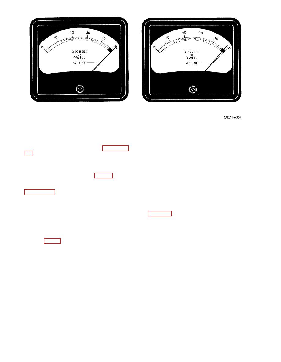
A
B
Figure 6. Dwell meter resistance readings.
e. Adjust the speed control handwheel
starting, operating, and stopping the dis-
(15) until the pointer reads 200 rpm on
tributor tester are contained in paragraph
the tachometer indicator (3), read the cam
29 below.
angle degrees on the dwell meter, and
check this reading against the cam angle
29. Cam Angle Test
of the distributor as specified by the ap-
plicable TM or by the manufacturer of the
Mount the distributor (par. 27). Zero
distributor.
t h e dwell meter (2), tachometer indicator
f. Turn the speed range selector (18)
(3), and vacuum gage (1), as prescribed in
to 0-2500 rpm and increase the speed to
2000 rpm. The reading on the dwell meter
in the "off" position.
(2) should be within two degrees of that
b. Set the cam angle selector (19) to the
obtained in e above.
"8 CYL" position and connect the distrib-
utor lead (7) to the distributor and the
hook-up for distributors with vacuum con-
ground lead (10) to the ground terminal (8)
trols, single condenser, two condensers
on the distributor clamp (26). If there is
with double breaker points, and distribu-
no reading on the dwell meter (2), rotate
tors with double lead condensers. On dis-
the distributor shaft until the distributor
tributors with double breaker points the
points (fig. 7) are closed and the dwell
meter shows a reading. Aline the meter
cam angle on each set of points are checked
separately and each must show the same
pointer with the "set line" mark on the
reading on the dwell meter. To block one
meter scale using the cam angle adjust-
ment (20).
set of breaker points open while testing
the other set, place a piece of fiber or any
c. Turn the cam angle selector to either
nonconducting material between the points.
the "4 CYL", "6 CYL", or "8 CYL" posi-
h. Turn the speed control handwheel (15)
tion, whichever corresponds with the num-
ber of lobes on the distributor cam.
clockwise and reduce the speed to its low-
est point on the 0-2500 range, switch the
d. Set the motor switch (17), to the di-
rection in which the distributor shaft is
speed range selector to 0-500 range and
driven on the vehicle, and turn the speed
adjust the distributor speed to 200 rpm
with the distributor still connected, and
range selector (18) to the 0-500 range.
12

