
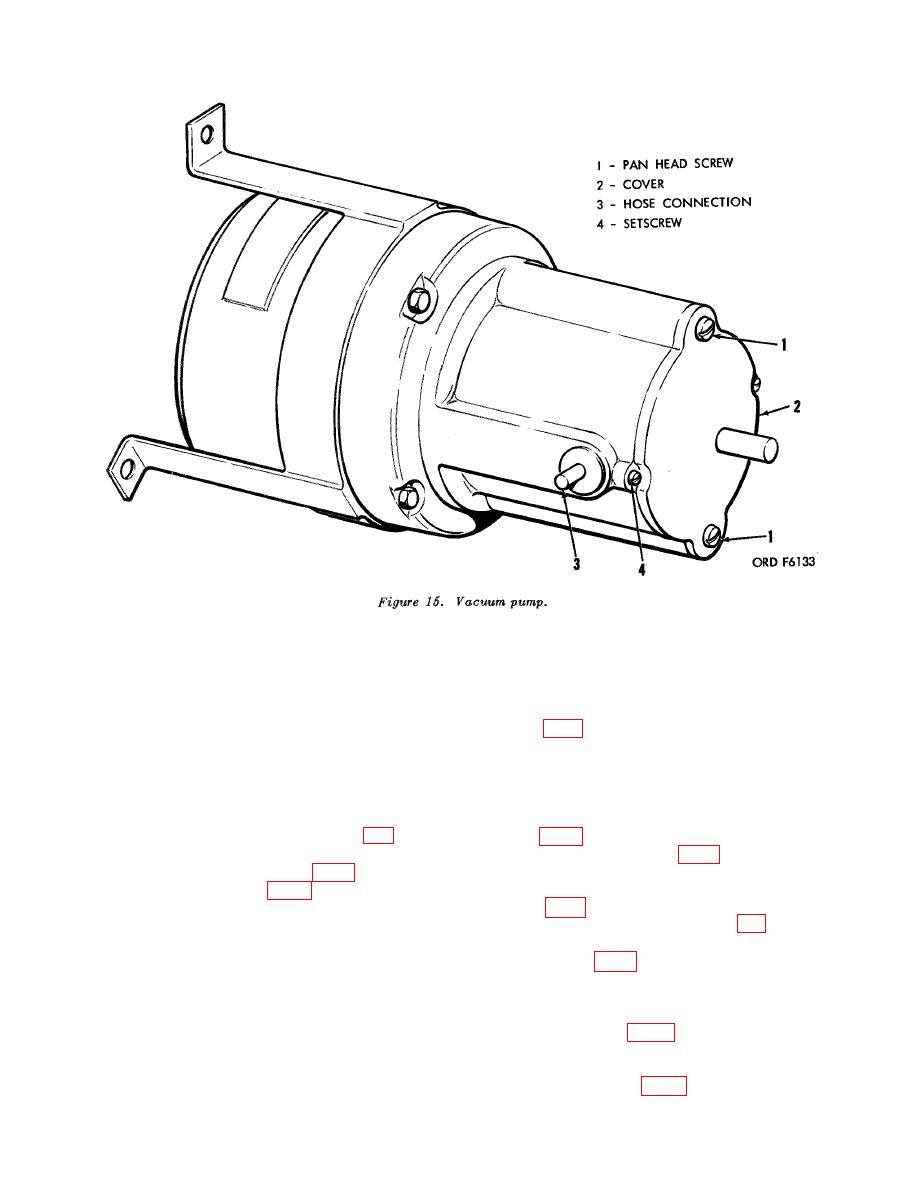
(3) Remove the two No. 6 x 5/8
(7) Adjust the position of the cylinder
in or out to allow maximum vac-
thread-cuting tipping screws (1)
uum as shown on the vacuum gage
bolting the cover (2) on the vac-
(10, fig. 4) and tighten the set-
uum pump.
(4) Apply several drops of SAE-20
screw (4) .
(8) Repeat the adjustment on the right
oil on each of the two felt washers
in the pump housing and secure
hand cylinder as prescribed in
the cover (2) on the vacuum pump
(6) and (7) above.
(9) Turn the vacuum pump control
with the two screws (1).
(9, fig. 4) counterclockwise until
(5) Connect the power cable (3A, fig.
the vacuum gage (10, fig. 4) reads
4) to the power source and turn
approximately 0.1 inch mercury
the power switch (3B, fig. 4) and
and turn the vacuum pump switch
pump switch (12, fig. 4) on.
(6) Holding the hose connection (3)
(12, fig. 4) off.
(10) Turn the power switch (3B, fig.
loosen the setscrew (4) on the left
hand cylinder just enough to allow
slight in and out movement of the
cable (3A, fig. 4) from the power
cylinder.
source.
Caution: Do not pull the cylin-
e. Installation. Place the tester in po-
der outward far enough to remove
sition in the case (1, fig. 4), aline the
it from the housing since com-
plete removal of the cylinder will
screw holes, and secure control panel
with the twelve No. 10 x 1/2 thread-cut-
make it necessary to repair the
ting tapping screws (24, fig. 4).
vacuum pump.
29
