
decalcomania located on the right hand end of
t h e test stand cabinet near the top center. It
contains instructions and a precaution to fill the
g e a r case chamber before operating the test
stand.
b . Varidrive Motor General Information
Plate. This plate is located on the front of the
stator housing of the varidrive motor. It speci-
fies the electrical and mechanical characteris-
tics of the motor, the type letters of the motor,
and the manufacturer's name and address, also
t h e "LO-VOLTS" and "HI-VOLTS" (fig. 13)
hook-up for the motor.
c. Varidrive Assembly General Instruction
Plate. This plate is located on the top front sur-
face of the varidrive assembly housing. It speci-
f i e s lubrication operating instructions (also
refer to fig. 62), and precautionary measures to
b e observed when operating and maintaining
the varidrive assembly.
d. Gear Case Oil Level Indicator Decalco-
m a n i a . The gear case oil level indicator is a
d e c a l c o m a n i a which is supplied with the test
stand unattached. After the gear case is filled
to the proper level (fig. 62) place this indicator
numbers 7336-1 and 7336-2) (4910-767-0218) -
decalcomania on the right hand end of the test
right rear view.
stand cabinet at the level of the oil in the oil
l e v e l sight glass (fig. 62). The indicator can
meters on both of the above test stands are of
then be used to maintain the oil in the gear case
the same value. The test stand model AGARTS,
at its proper level.
type II, part number 7336-3 (4910-767-0218)
e. Magnetic Motor Starter Drive Control
(not shown) is the same as the test stand under
T i m e Interval Caution Plate. This plate is
part number 7336-2, except it has a slide-out
mounted on the front of the cabinet of the test
t y p e platform for the batteries in the battery
s t a n d , above the drive control start and stop
c o m p a r t m e n t (fig. 9).
push buttons (33, fig. 16). It cautions the op-
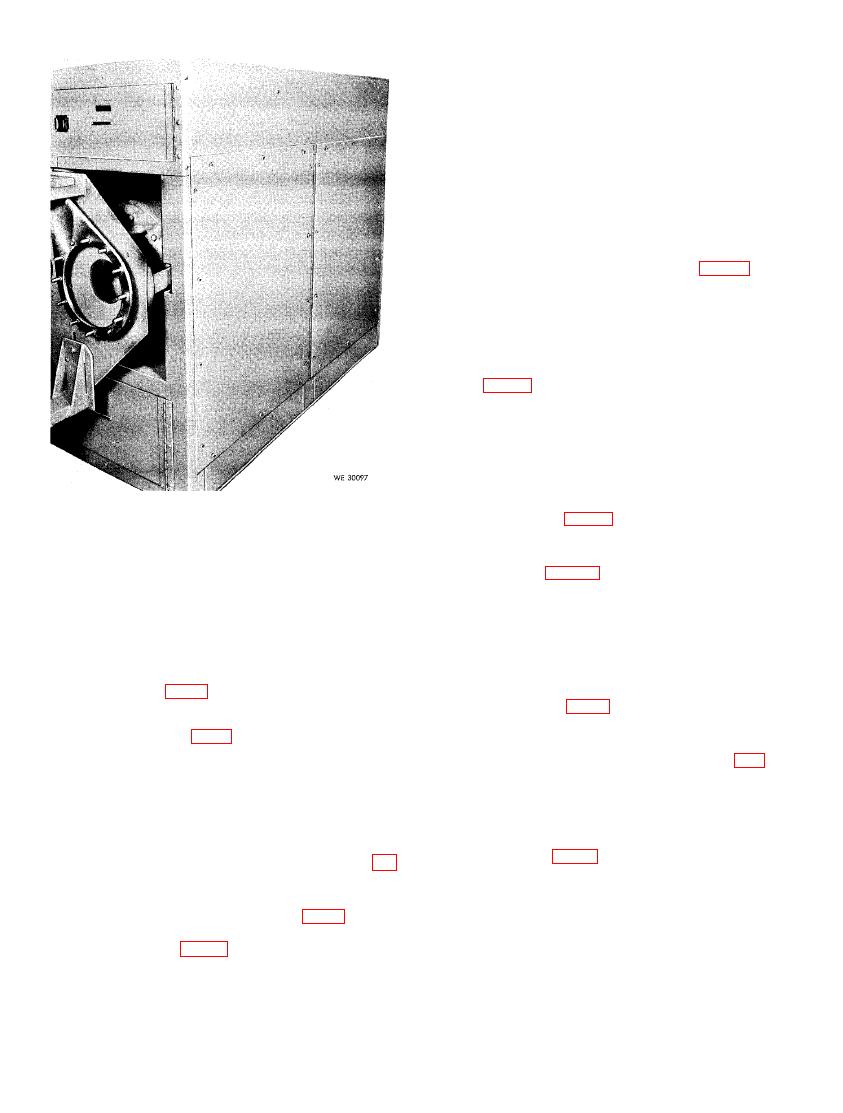
b. The test stand, type II, part number 7336
erator not to exceed depressing the start button
(4910-316-5252) (fig. 4) is basically the same
more than 30 seconds, otherwise, damage can
as model AGARTS, type II, part number 7336-1
develop within the magnetic motor starter (fig.
test stand in a above; the exception is that this
11).
m o d e l test stand has oblong shaped meters
f. Speed Control Precautionary Instructions.
which are larger and are not shock mounted. It
The speed control precautionary instructions is
has no manually operated battery charging unit
imprinted in the casting of the handle of the
and the equipment does not include the numbers
speed control (32, fig. 16). It alerts the operator
3144 and 3145 control box mounting plates (fig.
not to turn the handle when the varidrive as-
69). In the place of these mounting plates a con-
sembly is not running, otherwise, damage can
t r o l box mounting bracket is included on the
d e v e l o p in the chain drive mechanism of the
right hand side of the test stand (fig. 4).
speed control.
g. High-Speed Head RPM Range and Gen-
a. Gear Case Lubrication Caution Decalco-
e r a t o r Speed Caution Plate. T h i s p l a t e i s
m a n i a . The gear case lubrication caution is a
m o u n t e d on the left hand drive head of the
