
generator pulley and the pulley (8). Adjust
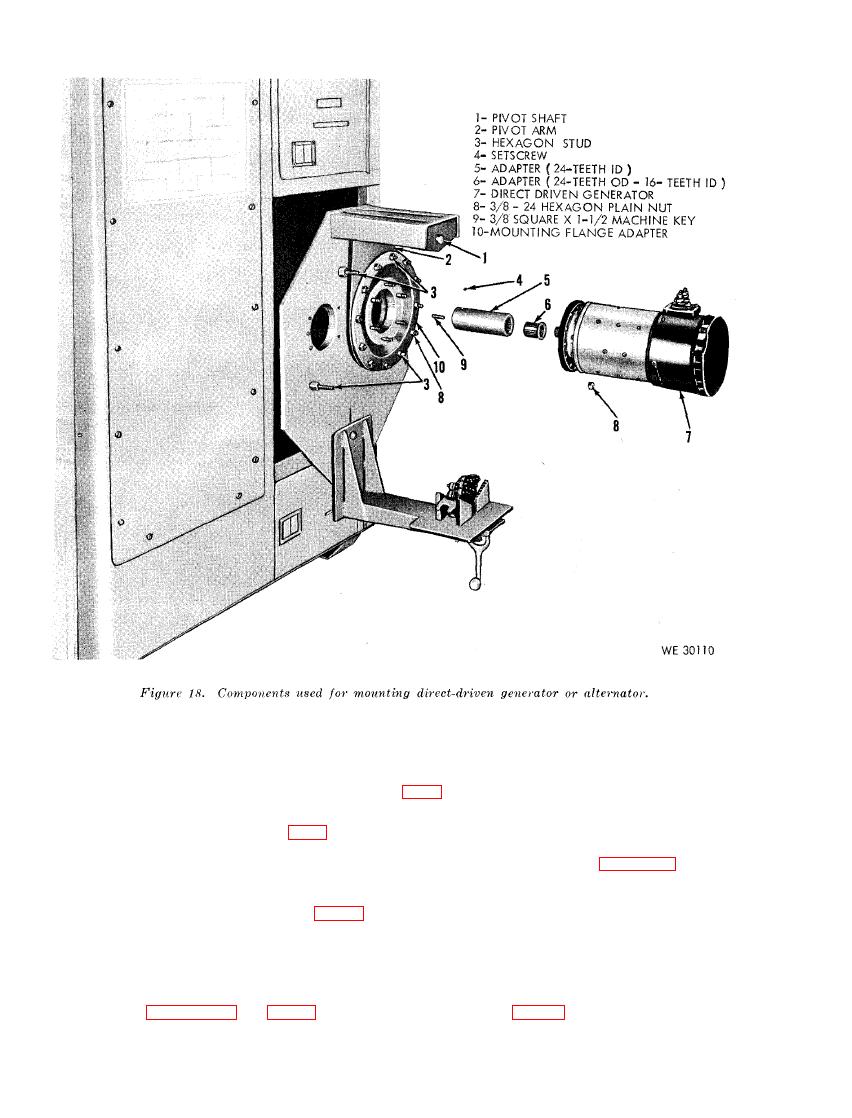
the adapter (5) with six hexagon plain nuts
(4).
t h e bracket (11) to obtain proper tension on
the V belts and tighten the locking handle (3-F,
c. Mount the pulley-driven generator (8) on
the generator and starter mounting bracket
alignment of the pulleys is required, slide the
(11) and secure with the chain vise (12).
chain vise (12) on the bracket (11) as needed.
Loosen the hexagon plain nut (3-E, fig. 7) un-
Tighten the hexagon nut under the chain vise
der the chain vise and slide the unit as required
to secure the vise in place. Figure 21 shows the
t o aline the pulley on the generator with the
p u l l e y - d r i v e n generator in the installed posi-
p u l l e y (8).
tion.
and adjust the generator and starter mounting
generator in the chain vise (12), be sure to
b r a c k e t (11) to the required height to allow
avoid clamping over nameplates and raised or
i n s t a l l a t i o n of the V belts (10) (install the
protruding surfaces. O n alternator use the
p r o p e r size V belts to match pulley (8), b .
vise mounting assembly and the chain mount-
above, refer to appendix II and fig. 68) on the
ing assembly (fig. 67) and do not clamp over
40
