
"MAX" position, the tachometer indi-
before tests are started to assure that
cator direct drive calibrating potenti-
the battery voltage is adequate for per-
ometer switch (19) to the "CAL POT"
f o r m i n g tests and to determine the
position, and the tachometer indicator
r a t e d voltage value of the batteries
high-low switch (18) to the "HI"
before charging. To perform this
position.
c h e c k , place the dc voltmeter range
(6) T u r n the tachometer indicator cali-
selector switch (22) in the "50V (X5)"
b r a t i n g potentiometer (58) until the
position for a 24-volt check (for a
s p e e d calculated in (1) above (8,000
6 - v o l t check set in the "10V (X1)"
r p m ) , is indicated on the tachometer
p o s i t i o n and for a 12-volt check set
i n d i c a t o r meter (3) (upper scale on
in the "20V (X2)" position). Place the
the meter).
load dc ammeter range selector switch
(7) A f t e r tests are completed, stop the
(15) in the "50A (X1)" position, and
varidrive assembly prescribed in para-
t h e voltage selector switch (41A) to
the "24V" position for a 24-volt check
or alternator from the test stand.
( f o r a 6-volt check set in the "6V"
p o s i t i o n and for a 12-volt check set
in the "12V" position).
Note. The key numbers shown below in parentheses
(2) Turn the dc voltmeter circuit selector
refer to figure 16.
s w i t c h (23) to the "BAT VOLTS"
a. Checking Battery Voltage Condition.
position and place the battery on-off
(1) The voltage condition of the batteries
within the test stand can be checked
s w i t c h (41B) in the "ON" position.
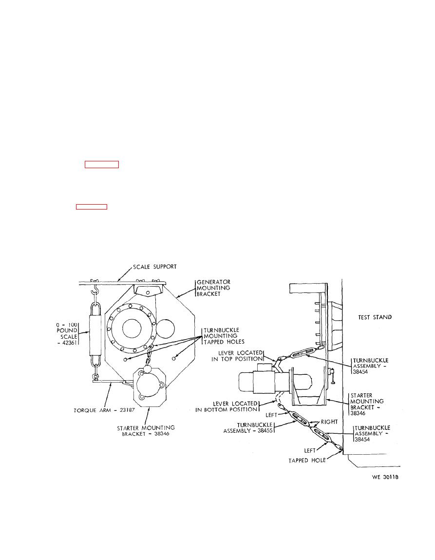
I n s t a l l a t i o n and mounting arrangement of turnbuckles for holding starter
pinion gear in position for engagement of torque arm hook or jaw.
