and G22-7F, 300-ampere generators.
Warning: Before reaching into the
(6) Check to see if the toggle switch on
high voltage compartment to change
the circuit breaker (fig. 11) is in the
t h e position of the drive reversing
" O N " position, then slide the safety
switch, place the toggle switch on the
clip (21-B) off the stop button (21-C)
circuit breaker (fig. 11) in the "OFF"
a n d depress the start button (21-A)
(do not hold the start button de-
position, as high voltage exists in the
p r e s s e d more than 10 seconds) to
s u r r o u n d i n g area of this compart-
ment.
s t a r t the varidrive assembly. Check
f o r correct rotation of the generator
p u l l e y (par.
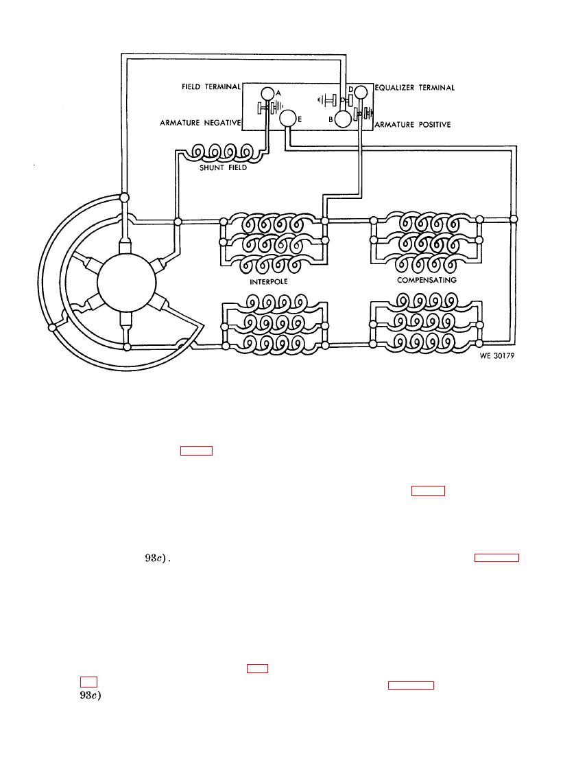
a 300 ampere generator shown in figure 42
is for a Jack and Heintz model G22-7F.
(7) If it is necessary to change the ro-
W h e n testing a model G22 or G22-2 Jack
t a t i o n of the generator (correct ro-
a n d Heintz generator the hook-up will be
t a t i o n is important, otherwise, the
t h e same except for the connection for the
g e n e r a t o r will have no output), stop
b l o w e r of the generator. This connection is
the varidrive assembly by pushing the
n o t required as the cooling device for the
models G22 and G22-2 is built within these
s t o p button (21-C), let the varidrive
generators by the use of a fan propelled by
assembly come to a complete stop, and
the generator shaft. When testing other
place the drive reversing switch (fig.
models of 300-ampere generators the hook-up
i l l u s t r a t e d in figure 42 may be followed as
a guide.
92

