
( f ) The foot-pounds indicated on the
(d) A d j u s t the setting of the starter
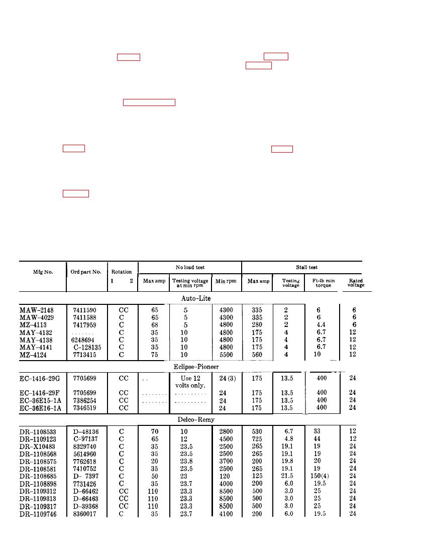
scale (fig. 61) should be 20 pounds
carbon rheostat (fig. 61) to near full
(table 9).
resistance position by rotating it in
(g) T u r n t h e s t a r t e r c a r b o n r h e o s t a t
the counterclockwise direction until
counterclockwise to reduce the cur-
a slight drag or pressure is felt. Do
r e n t (amperes) to a minimum. Do
not turn counterclockwise com-
t h i s rapidly when the 15 seconds
pletely (Refer to paragraph 81 for
details).
period is reached, (e) above.
(e) Place the starter test load disconnect
( h ) P l a c e the starter test load discon-
s w i t c h (15) in the "ON" position
nect switch (15) to the "OFF" po-
and turn the starter carbon rheostat
s i t i o n . Adjust the starter carbon
r h e o s t a t (fig. 61) to near full re-
mately 19.8 volts are indicated on
s i s t a n c e position by rotating it in
t h e dc voltmeter (4). The current
the counterclockwise direction until
(amperes) draw on the load dc am-
a slight drag or pressure is felt
m e t e r (1) should be 200 amperes
(par. 81).
(table 9).
(i) Press the stop button (25-C) of the
Caution: Application of the stall
drive control (25) and remove the
t o r q u e current (amperes) in ( e )
cable harness, test leads, scale, scale
above can damage the starter mo-
support torque arm, and starter
tor. Do not keep it applied for
(cranking motor) from the test
more than 15 seconds at a time.
stand.
132
