
(10) I n s t a l l the access cover (not shown)
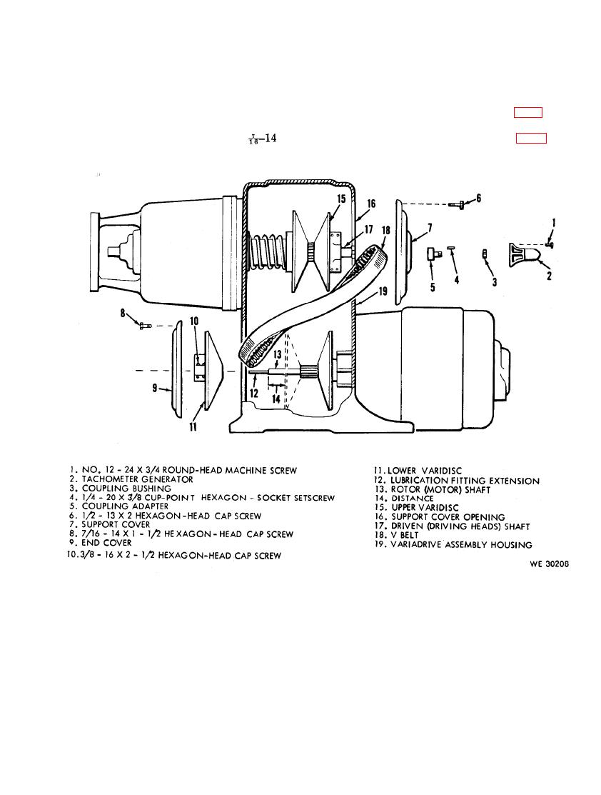
(8) Install the lubrication fitting extension
on the side of the varidrive assembly
(12) in the end of the rotor (motor)
h o u s i n g (19).
s h a f t (13).
(11) Install the two rear panels (fig. 3) and
(9) Place the end cover (9) in position on
generator, alternator, and starter
t h e varidrive assembly housing (19)
x 1
mounting bracket assembly (fig. 6) on
and secure with the four
the test stand.
hexagon-head cap screws (8).
153
