
TM 9-1550-416-14&P
receiver module and the servo/battery module are
NOTE
already installed in the aircraft.
In all connections to the receiver, the black (or
negative) lead is always to the outside edge of the
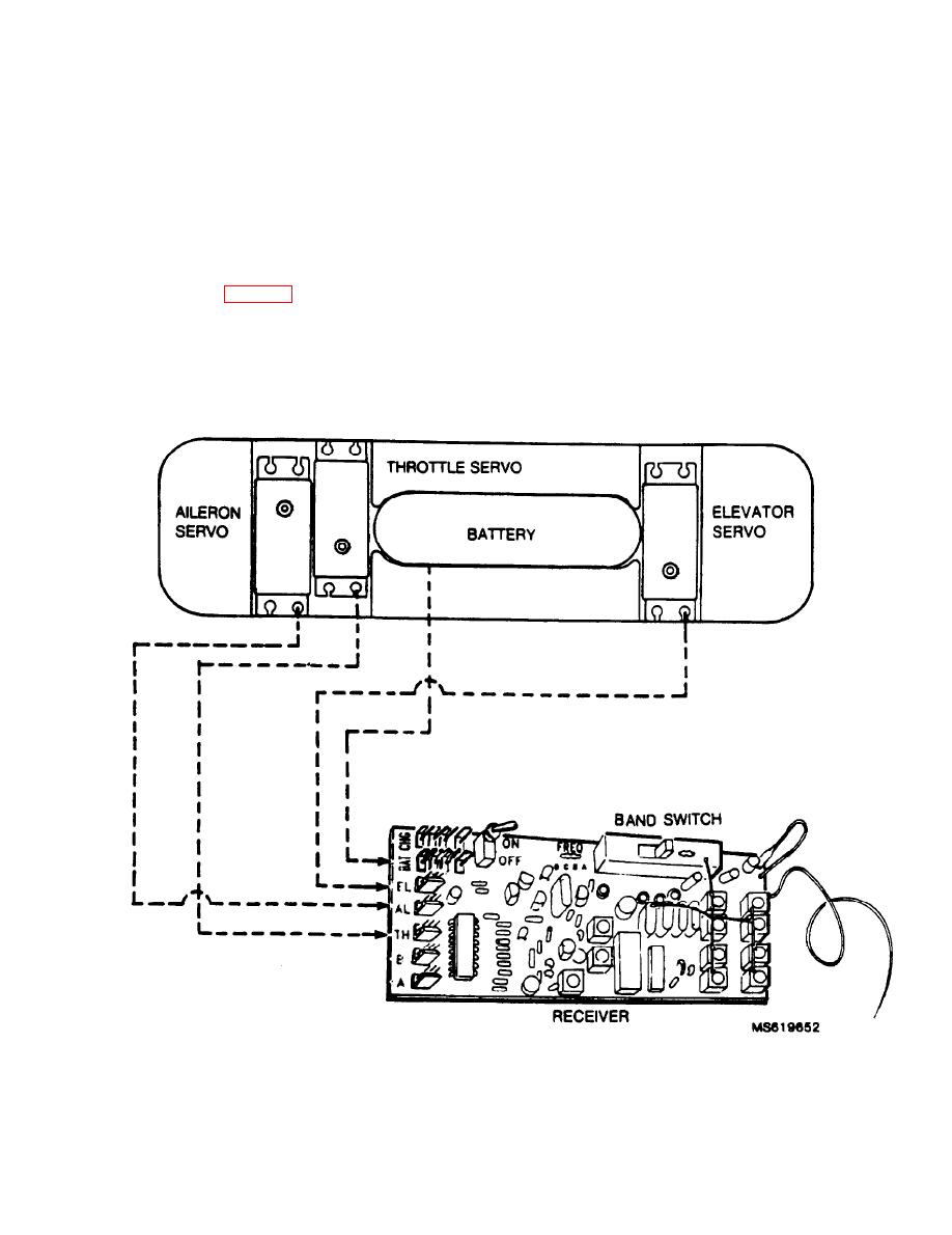
(a) Connect the elevator servo connector to
receiver.
the receiver elevator plug.
The receiver antenna is already plugged into the
receiver and threaded through the strain relief
(b) Connect the aileron servo connector to
hole.
the receiver aileron channel plug.
(7) Connect the servo/battery group to the
(c) Connect the throttle servo connector to
receiver. (See fig. 3-6) Feed the wire from the
the receiver throttle channel plug.
servo and battery pack individually through the
(d) Connect the battery connector to the re-
opening between the flight control compartment
and the receiver compartment. Be aware that the
ceiver power plug.
Figure 3-6. Servo/battery group to receiver interconnection diagram.
Change
1
3-7

