
TM 9-2330-356-14
e. Attach hoses (8 and 9) to valve of oil filter adapter
M970) (Fig. 7-12)
(11).
a.
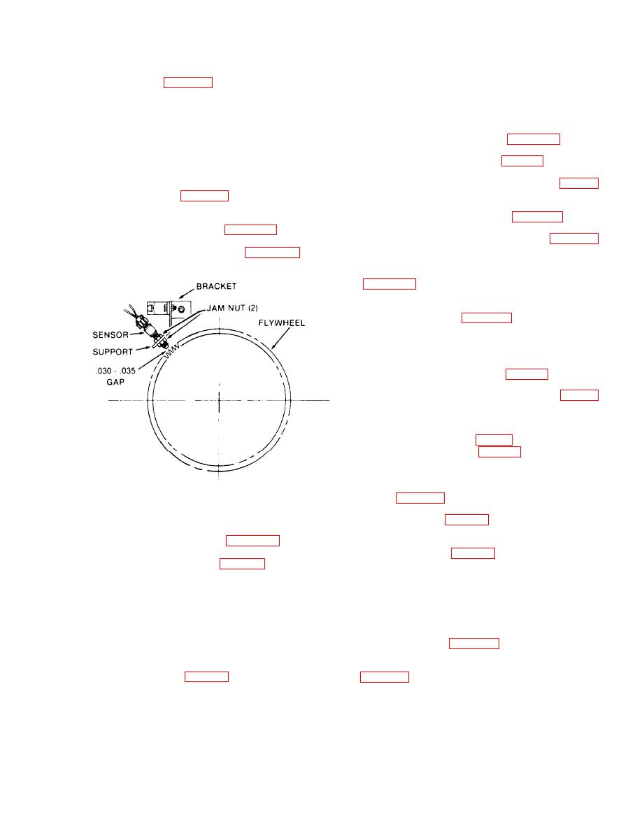
Position sensor in mounting bracket and install
Replace self-locking screw (1) and retaining
f.
bottom jam nut.
clamps (2).
b.
Connect two electrical leads to terminals on
sensor.
Bottom Cylinder Pan (3, Fig. 7-9)
a.
c.
Loosen top jam nut. Using a feeler gage between
(1) Position bottom cylinder pan (3, fig. 7-9) on
sensor head and flywheel, adjust sensor to obtain a gap of
engine. Install two screws (30).
.030- to .035-inch (fig. 7-42). Tighten both jam nuts
securely. Recheck gap setting.
(2) Replace all fuel lines (para 7-55).
d.
Install blower housing (para 7-60).
(3) Connect governor arm (3, fig. 7-14) to
governor linkage ball joint (22).
e.
Recalibrate the tachometer para 7-82).
(4) Connect the large lead to the manifold heater
injector pump lever, nylon tube to the oil pressure switch,
the two leads to the oil pressure switch, and the hot lead to
the fuel stop solenoid (para 4-22).
(5) Attach rear cylinder housing, blower housing,
and top air housing cover. Refer to steps b, d, and e.
Rear Cylinder Housing (1, Fig, 7-9).
b.
(1) Position rear cylinder housing (1, fig. 7-9) on
engine. Install three capscrews (28) and three washers
(29). Install two screws (27).
(2) If air shutter (fig. 7-8) is installed on engine,
install three capscrews (30, fig. 7-44). If air shroud is not
installed, do not install capscrews (30).
(3) Attach throttle cable to engine throttle
linkage (para 4-75).
TA100114
Figure 7-42. Tachometer Sensor Gap.
Air Shutter (Fig. 7-8).
c.
(1) Position air shutter on engine and install
three capscrews (30, fig. 7-44).
previously removed.
(2) If blower housing is installed, install two
screws (29) and washers (31). If blower housing is not
b.
Install oil cooler (6) on mounting bracket (7) and
installed, do not install the capscrews and washers.
secure with capscrews (3), lockwashers (4), and nuts (5).
(3) Thread high temperature switch leads
c. Mount mounting bracket (7) to engine using two
through hole in bottom of shutter box and attach to high
capscrews (10).
temperature switch (para 7-57).
d.
Insert hoses (8 and 9) through governor control
(4) Replace
high
temperature
switch
mounting bracket (12, fig. 7-14).

