
TM 9-2330-356-14
Replace governor arm (3, fig. 7-14) by tightening
f.
screw (3, fig. 7-28).
(10) on cylinder block (9). Install springs (18), washers (19),
Install blower housing (para 7-60).
g.
and seals (16) on push rod shields (17), and install
assembled push rod shields in cylinder block. Lift backside
of cylinder head in place. Use an anti-seize compound
Hone cylinder walls. Clean and oil the cylinder
a.
(item 5, Appendix E) on head bolt threads, and thread
walls. Install each piston in proper cylinder using a
bolts (4 and 6) and washers (7) into cylinder block (9). Do
suitable piston ring compressor. Each piston assembly
not tighten head bolts at this time.
should be installed with notch on piston toward front of
engine.
NOTE
Installing exhaust manifold now alines all four
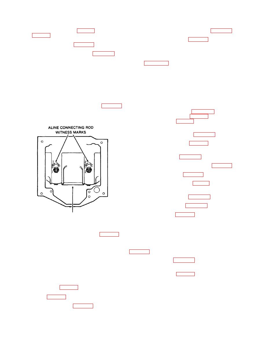
Position each connecting rod on crankshaft, oil
b.
exhaust ports with exhaust manifold before
the journal, and install rod cap with bearing half. When
the heads are torqued down.
installing rod cap, position so raised witness mark on the
forging matches the mark on connecting rod (figs. 7-27
and 7-39). Piston witness mark should face front, and rod
b.
Install exhaust manifold (para 7-52). Tighten
witness marks toward camshaft side of engine.
mounting screws to 1315 Ib.-ft. (table 7-3). Now tighten
head bolts to 44-46 lb.-ft. (table 7-3) following sequence in
figure 7-40.
c.
Install the intake manifold (para 4-82).
(3),rocker arm balls (2), and rocker arm nuts (1).
e.
Set valve clearance (para 7-89).
Replace rocker arm cover and gasket (para 7-45).
f.
Install fuel injectors (para 7-46).
g.
h.
Install the two baffles (34, fig. 7-9), and secure
with capscrew (32) and washer (33).
Install engine shrouding (para 7-60).
i.
a.
Place gasket (4, fig. 7-24) in position on each
CRANKSHAFT
cylinder head.
TA100111
Figure 7-39. Connecting Rod Installation.
b.
Install each rocker arm cover (3) to cylinder head
and secure with four screws (1) and lockwashers (2).
c.
Tighten capscrews to specified torque (table 7-3).
Tighten screws to 8-10 Ib.-ft.
NOTE
c. Replace shrouding previously removed
After installation of new connecting rod or
main bearings, clearances should be
Fuel Injectors (Fig. 7-23)
checked using plastic gage.
a. Ensure that old gasket material has been
d.
turn engine over by hand to see that all bearings
removed from injector (4, fig. 7-23).
are free.
b.
Assemble new nozzle gasket (5) adapter (6),
Install oil base (1, fig. 7-27) with a new gasket (2)
e.
gasket (7), and heat shield (8) on injector (4) and press
using ten screws (3) and lockwashers (4). Tighten to
together.
specified torque (table 7-3).
c. Install gasket (9) and injector and assembled parts
into cylinder head (10).
Install cylinder heads (para 7-44).
f.

