
TM 9-2330-227-14&P
LANDING GEAR AND BRACKET - CONTINUED
ACTION
ITEM
LOCATION
REMARKS
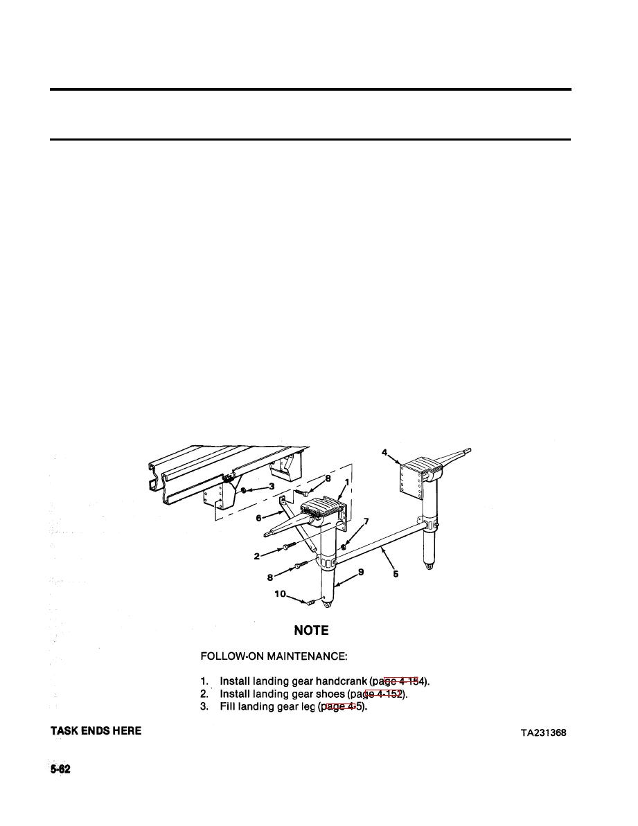
INSTALLATION - CONTINUED
Nine screws (2)
79. Right leg (1)
a. Screw together, and tighten using 3/4-
and nuts (3)
inch socket, ratchet handle with 1/2-
inch drive, and 3/4-inch open-end
wrench.
b. Repeat steps 78 and 79 on left
leg (4).
Brace (5)
Place in position, and weld (TM 9-237).
80. Right leg (1)
and left leg (4)
Right brace (6)
81. Right leg (1)
Place in position.
Nut (7) and two
a.
Screw together, and tighten using
82. Right brace (6)
screws (8)
15/16-inch socket, ratchet handle
with 1/2-inch drive, and 15/16-inch
open-end wrench.
b.
Repeat steps 80 and 81 for left brace.
83. Right lower leg (9)
Plug (10)
a.
Screw in, and tighten using 3/16-inch
socket-head screw key.
b.
Repeat on left leg.
