
TM 9-2330-235-14&P
4-38. TORSION BAR ADJUSTMENT (M514) (Con't).
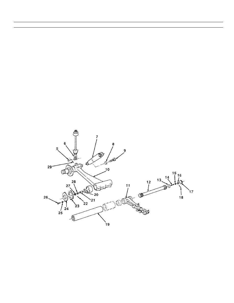
6. Remove cotter pin (22), nut (27), lockwasher (28), flatwasher (20), and stud (21) from outer end of torsion bar
(12). Discard cotter pin and lockwasher.
7. Use a brass drift to drive torsion bar (12) until expansion plug (17) is driven out of support (11). Discard expansion
plug.
8. Remove cotter pin (18), nut (16), lockwasher (15), and flatwasher (13) from stud (14) in inner end of torsion bar
(12). Discard cotter pin and lockwasher.
9. Use a brass drift to drive inward on torsion bar (12) until splines on bar are out of splines on cover (19) and
support (11).
10. Refer to amount frame was high or low as recorded in step 1.
(a) If frame was recorded low, carefully raise frame approximately the amount it was low until splines in cover
(19) and support (1 1) are alined. Drive torsion bar (12) outward into support and cover until splines are
centered.
(b) If frame was recorded high, carefully lower frame approximately the amount it was high until splines in
support (11 ) and cover (19) are ained. Drive torsion bar (12) outward into support and cover until splines
are centered.
4-92
