
TM 9-2330-271-14&P
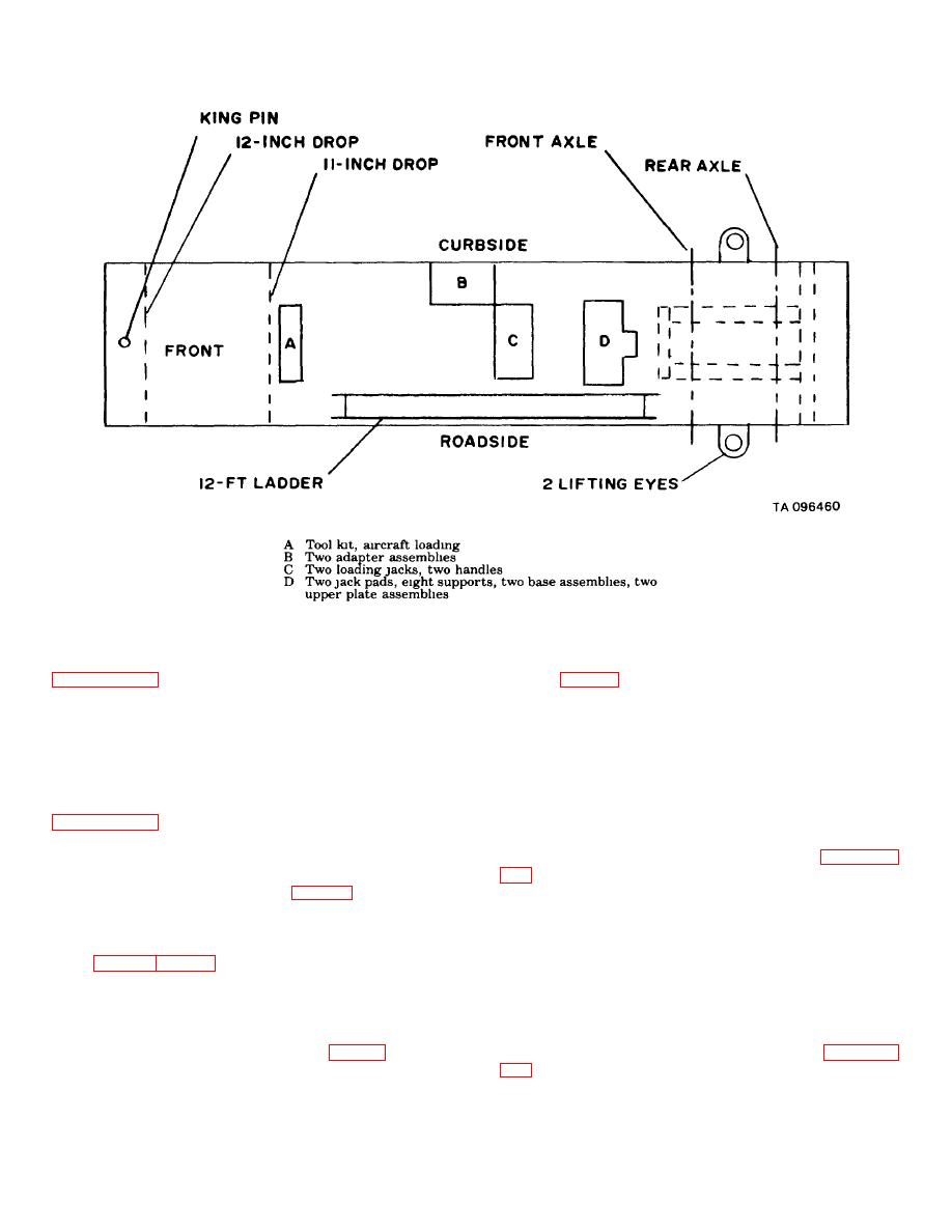
Figure 4-7. Location of stowage compartments, XM912, XM913.
(3) Perform steps (4) through (7) of
(10) Swing landing gears into the horizontal
position (fig. 4-5).
(4) Remove six cotter pins, nuts, washers,
(11) Detach towing vehicle and set it aside.
and screws securing the dolly assembly on the XM847,
(12) Load van body and dolly on the aircraft as
XM848, and XM849 semitrailers. To remove the dolly
directed by the loadmaster.
attaching hardware on the XM912 and XM913
d. Unloading Procedure.
semitrailers, remove two cotter pins, two nuts, six
(1) Perform steps 1 through 3 of paragraph 4-
washers, two bolts and four screws.
4d.
(5) Perform steps (9) through (11) of
(2)
Swing landing gears to the vertical
position and lower legs so that wheels contact the
(6) Move the K-Loader under the van body,
ground.
making sure that the inner skids of the van body match
(3) Perform steps 5 through 11 of paragraph
the rollers of the K-Loader, leaving the aircraft loading kit
stowage compartments accessible (fig. 4-4).
(4) Insert dolly in position from the rear and
(7) Remove aircraft loading jacks, stands and
lower rear end of van body.
adapters and stow them along with the tool box in their
(5) Secure the dolly assembly on the XM847,
respective stowage compartments underneath the van
XM848 and XM849 semitrailers with six screws,
body (figs. 4-6 and 4-7).
washers, nuts, and cotter pins.
(8) Move K-Loader forward until it almost
(6) Secure the dolly assembly on the XM912
contacts the landing gears.
and XM913 semitrailers with two bolts, washers, nuts,
(9) Secure van body to the K-Loader by
and cotter pins at the rear end and with four screws and
means of the tiedown provisions in the sidewalls and
washer at the front end and sides.
tiedown rings provided by the Air Force (fig. 4-5).
(7) Perform steps 12 through 14 of paragraph
4-6
