
TM 9-2330-271-14&P
(4) Depress air spring to retract upper
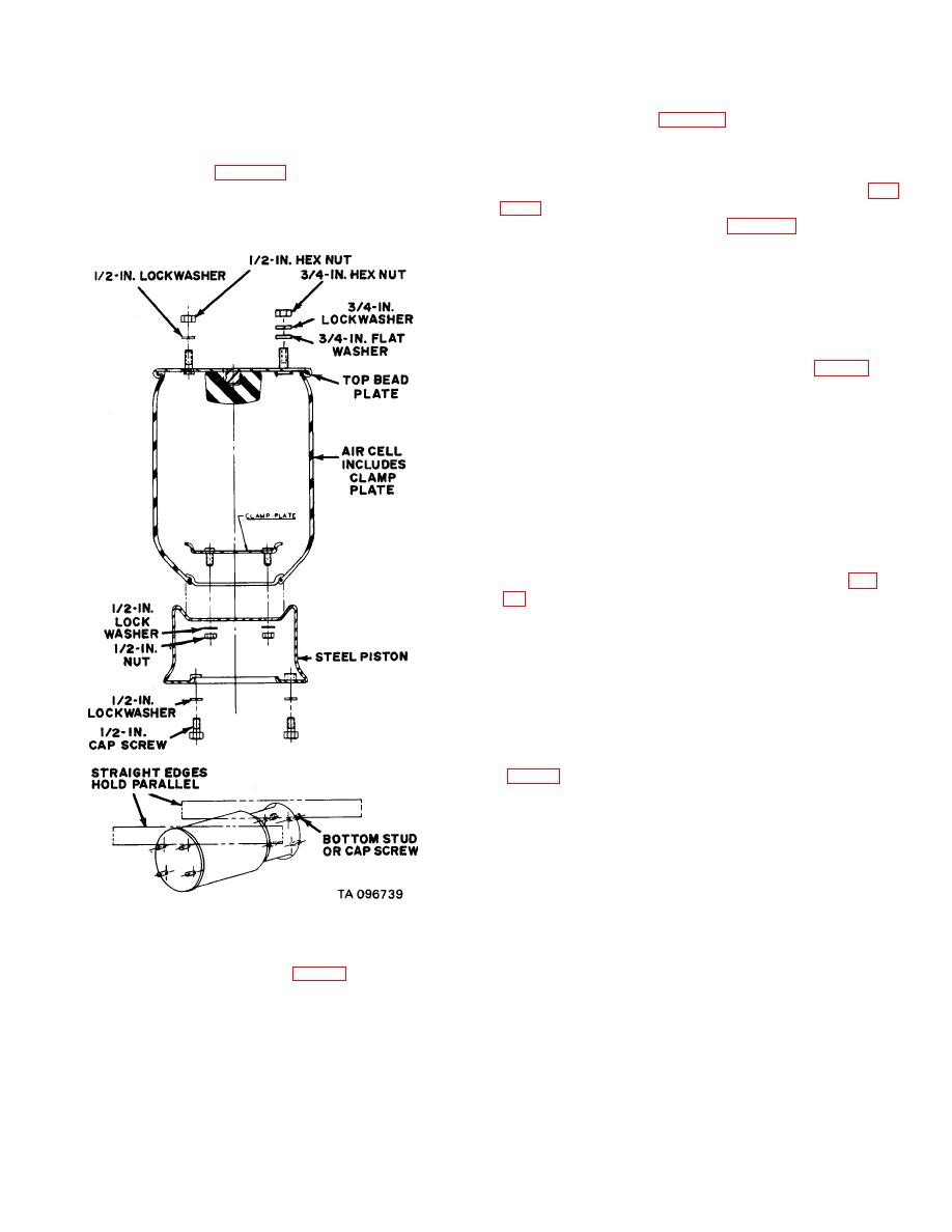
(3) Start the 1/2-inch nuts and lock washers
mounting studs from frame and remove air spring with
on studs inside piston (fig. 4-43). Do not tighten.
lower piston attached.
(4) Rotate piston so that mounting studs in
(5) Turn air spring assembly upside down and
bottom of piston are parallel with mounting studs in top
remove 1/2-inch nuts (fig. 4-43) from inside of piston.
bead plate.
Tap down on clamp plate studs until air cell separates
(5) Start cap screws in bottom of piston (fig.
from piston.
bottom cap screws as shown in fig. 4-43. Adjust piston
studs until straight edges aline.
(6) Tighten nuts inside piston to a torque of
50 lb-ft.
(7) Recheck for proper alignment of top and
bottom studs.
(8) Pressure test at 40 psi and check for
leaks with soap solution.
(9) Place air spring assembly (15, fig. 51) on
pad of equalizing arm and install lower mounting cap
screws (17) and lock washers (13). Tighten to a torque
of 25 lb-ft. maximum.
(10) Depress air spring. Guide upper studs
into air spring mounting plate (14). Secure with nuts (11
and 12), lock washers (10 and 13), and flat washer (9).
Tighten to a torque of 25 lb-ft. maximum.
(11) Reconnect height control valve linkage
and air line (8).
(12) Recheck for leaks at operating pressure.
(13) Remove blocking and jacking equipment.
f.
Removal of Axle Connection Components (fig.
(1) Remove all weight from suspension by
blocking up semitrailer and jacking up axle.
(2) Exhaust all air from air springs by
disconnecting linkage to both height control valves and
rotating actuating arms down.
(3) Remove axle cap nuts (23), flat washers
(22), and bolts (6) and (7) and remove axle connection
components (18 through 21).
g. Installation of Axle Connection Components
CAUTION
The axle connection cap (21) must be
drawn down so that a metal to metal
contact exists
between
the
axle
connection cap and its mating part (16).
Tighten nuts to a torque of 300 lb-ft.
(1) Position axle connection components (18
through 21). Make sure that groove in axle pad (20)
Figure 4-43. Air spring replacement.
matches bottom tongue on axle adapter (19), and that
metal tongues on axle connection cap (21) fit into
e.
Installation of Air Spring (fig. 51).
respective slots provided in mating parts.
(1) Position new air cell, right side up, over
(2) Secure axle connection components (18
piston. Position clamp plate so that studs hang down
through 21) with bolts (6) and (7), flat washers (22) and
through opening in air cell.
nuts (23).
(2) Carefully set air cell down on piston so
(3) Reconnect linkage to height control
that studs go through holes in piston.
valves.
4-63
