
TM 9-2330-271-14&P
(2) Pressurized air from the towing vehicle air
system is used to supply the two air springs used with
the air mounted fifth wheel kingpin. The preset height
control valve regulates air flow to the spring m proportion
to the load until the proper design height is obtained.
(3) When the semitrailer is uncoupled from
the towing vehicle, the air springs automatically exhaust
air until the bolster plate comes to rest on rubber
bumpers inside the springs. A valve and filter assembly
maintains safe air brake pressure and clean air and is
set at 65 psi.
(4) A smooth ride is obtained through the use
of a height control valve (fig. 4-41) which meters the
amount of pressurized air required to compensate for
varying trailer loads. Air is metered through the valve
any time the trailer air system is coupled to the charged
air system of the towing vehicle. The actuating arm
detects movement above or below design height and
causes the valve to compensate by exhausting or
supplying air as required.
(5) Loss of air pressure or air spring
deflection by off center load will cause the actuating arm
to move up. Up movement opens the intake valve and
allows supply air to pass through to the air springs.
When the arm moves down, indicating excessive air
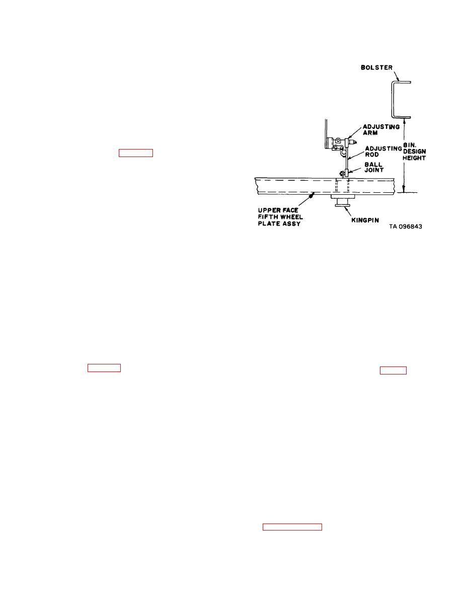
Figure 4-45. Ride height dimension adjustment, air
pressure, the exhaust valve opens, allowing excess
mounted kingpin
pressure to vent to the atmosphere.
(6) A safety check valve in the intake fitting
(2) Loosen height control
valve adjusting rod
prevents pressure loss if supply pressure is lost. A 5-
and raise the adjusting arm when
height is too low.
second time delay is incorporated in the valve to prevent
Tighten adjusting rod.
unnecessary actuation while negotiating uneven terrain.
(3) Loosen height control
valve adjusting rod
Valve hunting action is eliminated by 3/8-inch dead zone
and lower the adjusting arm when
height is too high.
in the valve action.
Tighten adjusting rod.
b. Adjustment of Height Control Valve.
(1) Design dimension between bottom of
4-59.
Replacement
of
Air
Mounted
Kingpin
bolster and upper face of fifth wheel plate is 8 inches
Components
when fifth wheel plate is in position parallel to the
semitrailer frame (fig. 4-45). The design height can vary
a.
Removal of Kingpin Air Spring (fig. 44).
plus or minus one-eighth of an inch with-out adverse
(1) Extend landing gear and uncouple
effect on operation.
semitrailer from towing vehicle.
(2) Disconnect linkage from height control
valve and depress actuating arm to exhaust air pressure
from air springs.
(3) Place fork lift or other suitable lifting or
blocking device under fifth wheel plate to carry weight of
assembly.
(4) Disconnect air line at top of air spring (12)
and remove upper mounting screws (5) and lock
washers (6).
(5) Remove screws (13) attaching air springs
to fifth wheel plate (11).
NOTE
It may be necessary to disconnect shock
absorbers (10) before accomplishing the
following step. Refer to procedures in
4-65
