
TM 9-2330-294-14
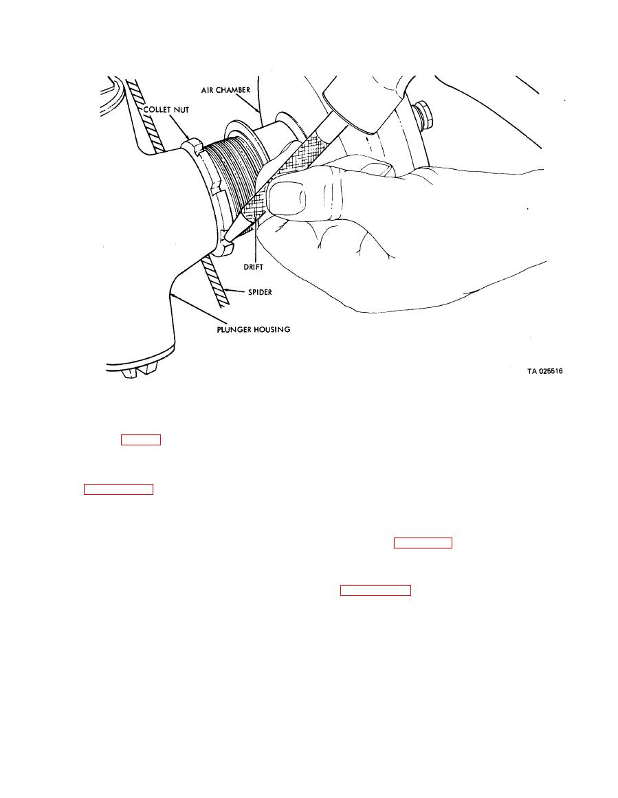
Figure 4-33. Air chamber assembly removal or installation.
and
wipe plunger housing wedge assembly chamber with
Inspection
Assembly
4-34. Wedge
clean rag.
Replacement
(2) Install wedge assembly into the plunger
housing. C h e c k for correct roller-plunger
a. Removal.
engagement by:
(1) Remove brake air chamber assembly or fail-
(a ) Observing the ears on wedge assembly
safe chamber assembly by following procedure in
are in corresponding slots in wedge bore of plungers,
(b ) Pushing on wedge rod by hand, while
(2) Remove wedge assembly by pulling straight
checking for plunger and brake shoe lift, and
out of plunger housing.
(c ) Measuring the standout of the wedge rod
b. Inspection. Clean wedge assembly thoroughly
from the end of the threaded plunger housing bore
with mild soap solution and dry with low pressure
per inset of figure 4-34. When properly assembled,
compressed air. Inspect for damaged or inoperable
the wedge rod standout is 2/14 inches.
parts. Replace wedge assembly, if necessary.
(3) Install brake air chamber assembly or fail-
c. Repair. Repair of wedge assembly should be
safe chamber assembly by following procedure in
accomplished by direct support maintenance
personnel.
d. Installation.
(1) Without disturbing position of plungers,
