TM 9-2330-294-14
(3) Assemble gasket and anchor plunger guide
(a ) Apply film of grease (BRH) to inside
into plunger housing. Make certain guide end enters
surfaces of seal assembly.
(b ) Mask brake shoe web slot in plunger
the plunger keyway slot, so plunger can slide freely
nose with masking tape to protect seal. Carefully
in housing bore. Tighten guide to 15-20 lb ft torque.
(4) Coat the inside and outside surfaces of both
push the double-lip seal assembly onto the plunger,
the adjusting plunger and the adjusting sleeve with
stretching the outer seal lip over the plunger nose
grease (BRH).
end, until the inner seal is completely in the second
plunger groove and the outer seal lip is in the first
NOTE
plunger groove. Remove masking tape from plunger
The adjusting pawl has teeth on one end,
flats on the side, and a chamfered edge in the
nose.
other end. Coat pawl with grease (BRH) and
(2) Install anchor plunger into plunger housing
insert it into the guide hole, teeth first, and
in the following manner:
-IMPORTANT- with chamfer toward the
(a) Coat all plunger bores with grease
(BRH).
brake shoe. This alines the pawl and ac-
tuator teeth and the flats with the keyway
NOTE
slot. Be sure pawl is fully inserted into the
Take care that anchor plungers marked "L"
plunger housing slot.
are installed in left-hand brakes and anchor
Place the adjusting plunger into the plunger
plungers marked `` R" are installed in right-
housing, alining plunger keyway slot with the guide
hand brakes.
hole, and assemble adjusting pawl, gasket, spring
(b) Coat entire anchor plunger with grease
and guide assembly into the plunger housing. Turn
(BRH), packing cavity behind seal assembly, and
guide assembly in one or two turns.
insert plunger and seal assembly into housing with
(5) Assemble the plunger seal onto the ad-
plunger keyway slot alined with anchor plunger
justing actuator in the same manner described in (1)
guide hole. The plunger must go all the way into the
above, Insert actuator and seal assembly into the
plunger bore and seat on the bosses at bottom.
adjusting plunger, wiggling it, so the guide pawl and
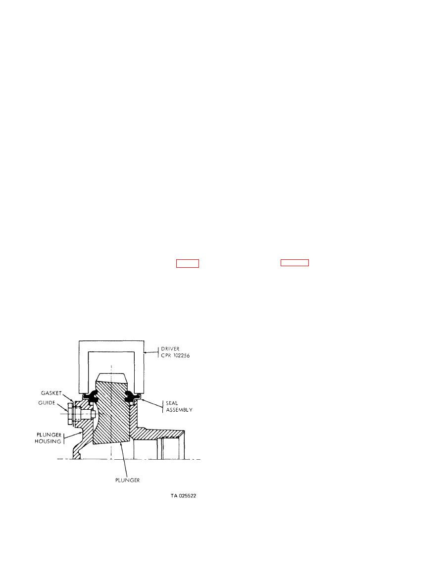
(c) Seat plunger seal assembly in plunger
actuator teeth mesh (fig. 4-40). If necessary, back off
housing with seal driver tool (CPR 102256) (fig. 4-
guide assembly, to enable meshing of pawl and
39). Driver must be centered over seal retainer to
actuator teeth. Push the actuator into the plunger
prevent damage to seal assembly.
until it bottoms.
Figure 4-39. Seating plunger seal assembly in plunger housing.

