
TM 9-2330-356-14
(9) Tighten lower heat sink screws (15) and check
all leads for proper routing. Ensure that no lead is pinched
under heat sink.
(10) Reinstall stator and terminal nuts. It is
advisable to aline stator (14) and housing (31) by
temporarily installing the through bolts (5).
(11) Press drive end bearing (8) into housing (7),
and reinstall bearing retainer (9) and four screws (10).
Figure 7-68. Heat Sink Mounting.
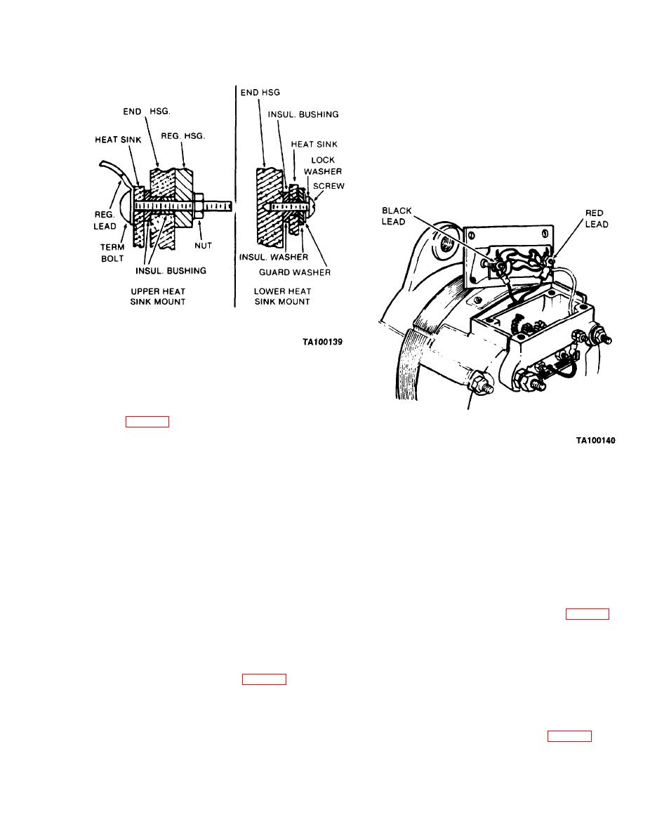
(3) Install insulating bushings (26) into heat sinks
(21 and 22). Position heat sinks in the slip ring end housing
(31) and fasten with two capscrews (15), lockwashers (16),
guard washers (17), and insulating washers (18). Do not
tighten (fig. 7-68).
(4) Install capacitor (25), clamp (24), and three
screws (23).
(12) Press drive end housing (7) and bearing (8)
(5) Replace the gasket (36) and regulator housing
onto rotor shaft.
(37).
(13) Install rotor (12) and housing (7) assembly
into stator (14) and slip ring end housing (31) assembly,
NOTE
being sure to aline mounting ears.
Be sure mating surfaces of heat sinks,
(14) Install three through bolts (5), washers (6),
terminals, and terminal screws are clean and
and self-locking nuts (32). Tighten nuts to 50-60 lb.-in.
free of paint to ensure a good electrical
Place a small amount of SRI 2 grease in housing and
connection.
reinstall the metal dust cap (33) by carefully pressing it
into place.
(6) Install the regulator lead wires to the
terminal bolts. Red wire goes on the positive terminal
(15) Install diode trio and three nuts (fig. 7-65).
screw (19), and black wire goes on negative terminal screw
(16) Insert outer brush and spring assembly (44)
(20).
into the housing (37), and compress the brush spring. Use
a small screwdriver or similar tool. While holding the
(7) Install terminal bolts through heat sinks, slip
spring compressed, insert a pin through the hole in the
ring end housing (31), and regulator housing (37). Ensure
rear of the housing so the spring will be held in a
that red and black regulator leads (fig. 7-69) are properly
compressed position. (A suitable pin can be made from a
routed through cutaway section of end housing (31).
piece of 1/16-inch drill rod.) Install and compress the
remaining brush and spring assembly (44) in a similar
(8) Install two nuts (38) on terminal screws (19
manner. Hold the spring in a compressed position by
and 20). Tight en nuts. Loosely install two washers (39) and
nuts (40).
pushing the pin farther into the housing (fig. 7-70).
7-61
