
TM 9-2330-356-14
Carefully separate the intermediate housing and seal
plate as an assembly from the volute (7). Discard gasket
(11).
(a) To remove impeller
(10),
use
instructions in paragraph 8-3c.
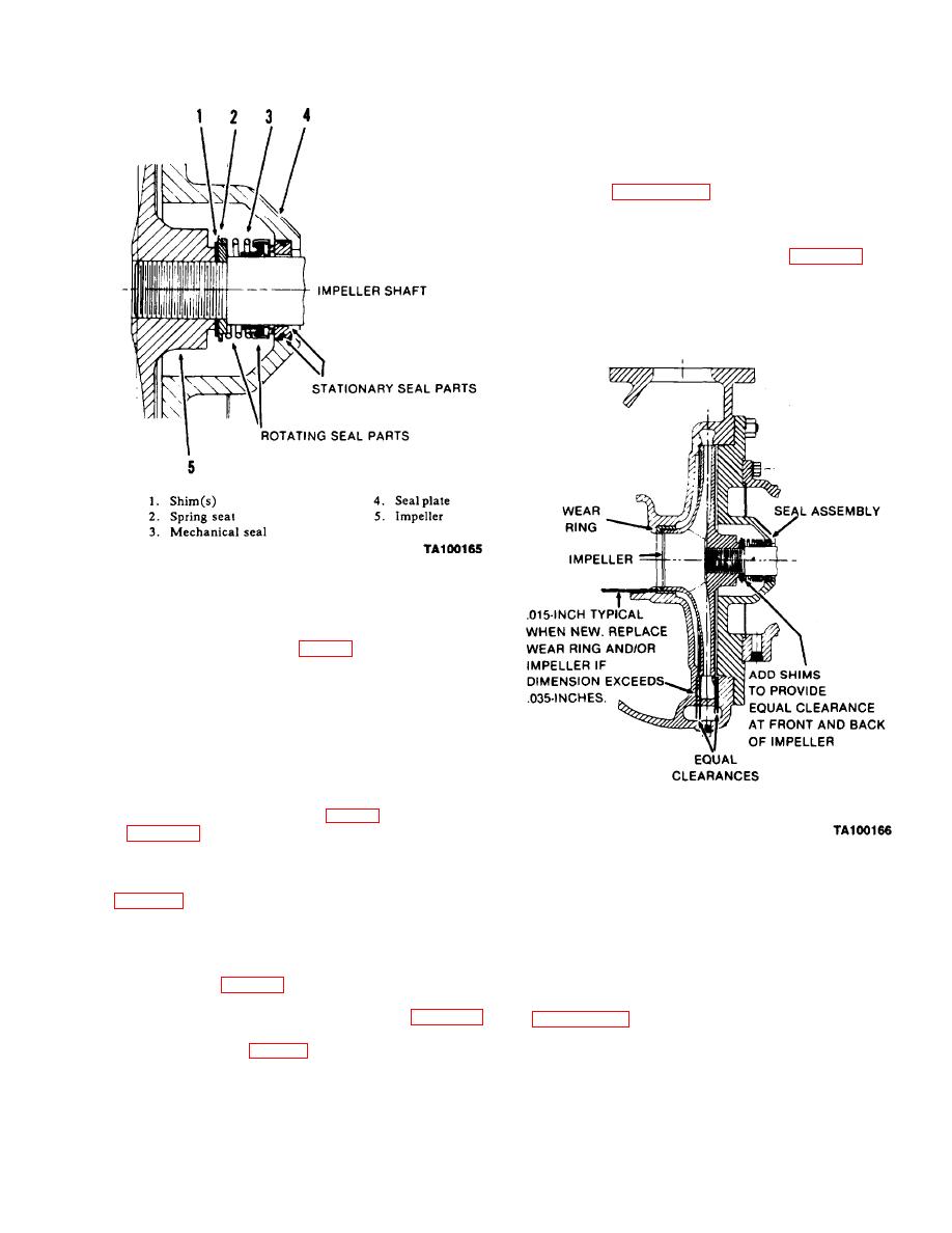
(b) The enclosed impeller uses a wear ring
(9) to keep internal pump leakage at a minimum. When
the clearance exceeds the limits shown in figure 8-4, the
impeller and/or wear ring must be replaced.
(c) To remove wear ring (9), use a suitable
puller.
(8) After adjustment for proper running
clearance is made, tighten impeller securely.
new wear plate in pump casing and fasten with two nuts
(25) and lockwashers (26).
(10) Put anew gasket (19) over studs (22) of volute.
Install seal plate assembly and intermediate housing
assembly (3). Check and adjust the clearance between the
impeller vanes and the wear plate (step e). Install
lockwashers (2) and nuts (1) and tighten securely.
(11) Install pipe plug (13, fig. 8-2). Refer to Section
I, Chapter 3, and fill the intermediate housing with the
proper lubricant.
(2) Seal Plate and Mechanical Seal. The
Install pump and coupling
g. Installation.
arrangement for the mechanical seal is the same as the
4-inch pump. Use the following procedure to remove the
seal:
Pump, 3-inch (M970 and M970A1)
(a) Remove pipe plug (34) on bottom of
a. Air Leakage Test. Perform preliminary test before
intermediate housing and drain lubricant.
removing pump (para 8-3a).
(b) Remove impeller (10) using instructions
b.
(c) Remove eight capscrews (28) and
Disassembly (Fig. 8-5).
c.
lockwashers (27) and pull the seal plate (15) and
mechanical seal (14) from the impeller shaft as an
(1) Impeller (10) and Wear Ring (9). For access to
assembly.
the impeller, remove nuts (17) and lockwashers (16).
