
TM 9-2330-357-14&P
4-50. OUTRIGGER DRIVE MOTOR REPLACEMENT.
This Task Covers:
a. Test
c. Installation
b. Removal
Initial Setup:
Equipment Conditions:
Materials/Parts:
Outriggers lowered to ground (para 2-12).
One gasket
Four self-locking screws
Tools/Test Equipment:
Personnel Required: Two
General mechanic's tool kit
Common no. 1 shop set
a. TEST
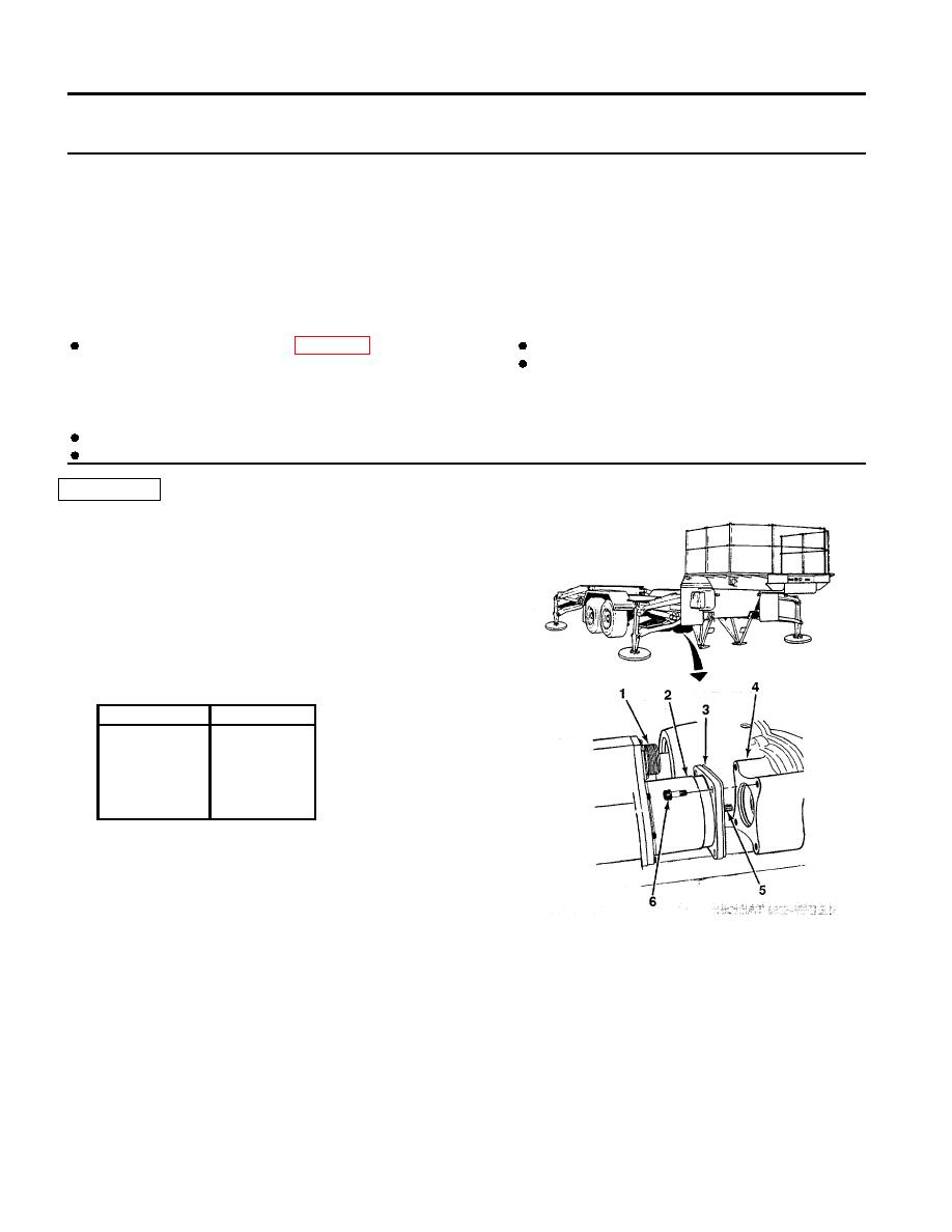
1. Disconnect outrigger motor cable from connector (1).
NOTE
When performing step 2, multimeter should be
set on highest scale.
2. Check continuity of pins in connector (1) of drive
motor (2) as shown:
Pins
Ohms
A to D
20
C to B
0
H to G
0
F to E
0
3. If continuity check shows correct values, check
each pin to ground.
4. If pin F to pin E shows open, thermal switch is de-
fective, notify Direct Support Maintenance.
5. If any continuity check (other than pin F to pin E)
shows open, field widings are defective and out-
rigger drive motor should be replaced.
6. Connect outrigger motor cable to connector (1).
4-104
