TM9-2330-368-14 & P
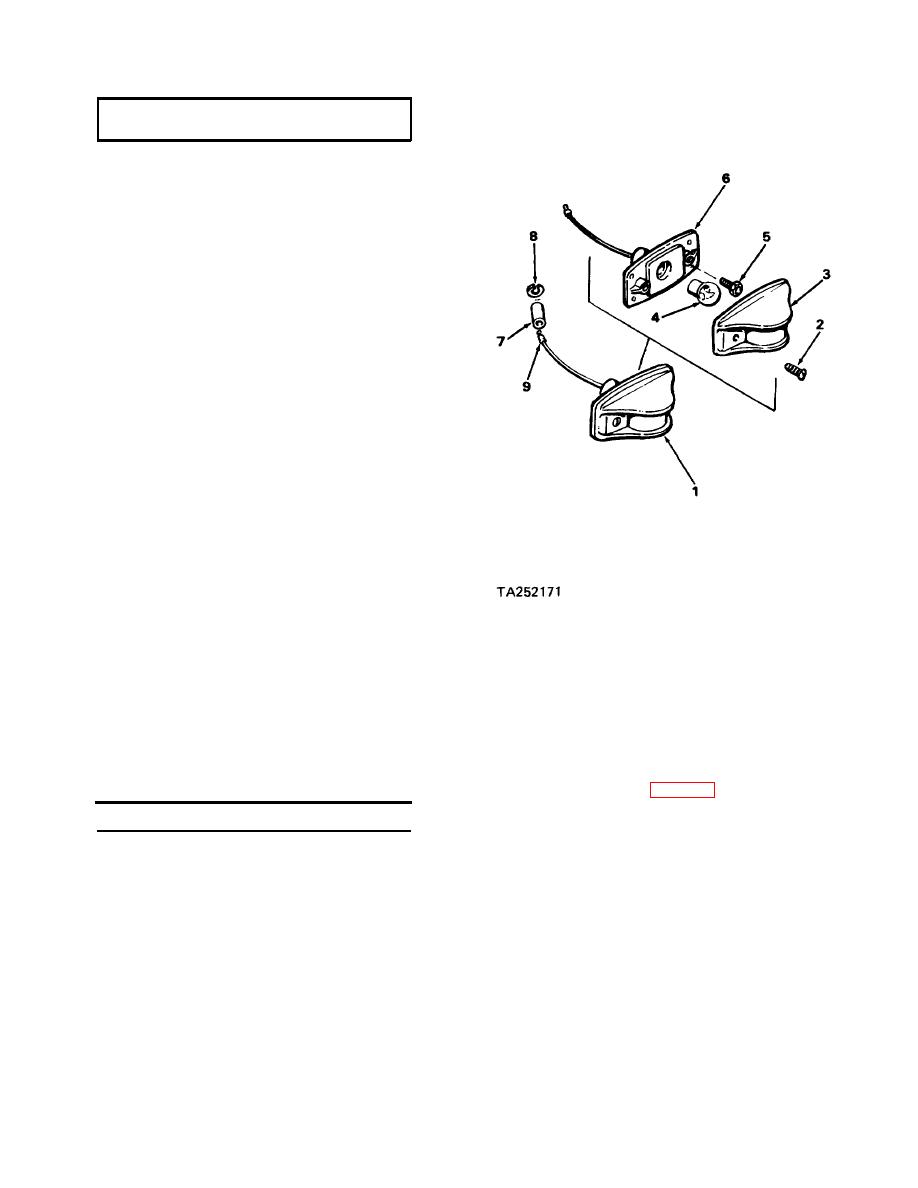
4-11. CLEARANCE MARKER LIGHTS
Materials/Tools
General mechanics tool kit
All clearance marker lights (1) are identical except
for the lenses.
a. Removal.
(1) Disconnect light connector from har-
ness connector.
(2) Remove two screws (2) and lens (3).
(3) Remove lamp (4).
(4) Remove two screws (5) and light hous-
ing (6).
(5) Push shell (7) back on wire and remove
C-washer (8) and shell (7). Remove
terminal (9) if damaged.
b. Installation.
(1) Install terminal (9) if removed. Insert
terminal (9) through shell (7). Install
C-washer (8) on terminal (9) and pull
shell (7) over terminal.
(2) Check for continuity between wiring
(2) Mount light housing (6) to trailer with
harness connector pin D and the chassis.
two screws (5).
If the circuit is open, repair ground
lead on wiring harness.
(3) Install lamp (4).
(3) Check for grounds between wiring har-
(4) Install lens (3) with two screws (2).
ness connector pins A, B, C, E, F and J
and pin D (ground). (Refer to schema-
(5) Connect connector to wiring harness.
tic diagram, page 4-2 1.) There should
be an open circuit between the con-
4-12. TESTING ELECTRICAL SYSTEM
nectors pins. If there is continuity be-
tween any connector pin as specified,
Materials/Tools
that circuit is grounded and the wiring
harness must be repaired or replaced.
a. Check for Grounds.
(4) Remove all lamps from lights (para.
4-10 and 4-11).
(1) Disconnect all wiring connectors at the
lights. Be sure identification markers
(5) Check for grounds from each light lead
are present on individual wires before
wire and the chassis (ground). There
disconnecting. If not, tag wires.
should be an open circuit between each
NOTE
lead wire and the chassis. If there is
Check for continuity on grounds
continuity on any lead wire, the wire
is grounded and must be repaired or the
using the multimeter on a low
light replaced.
ohms scale.
4-17

