TM9-2330-374-14&P
1.
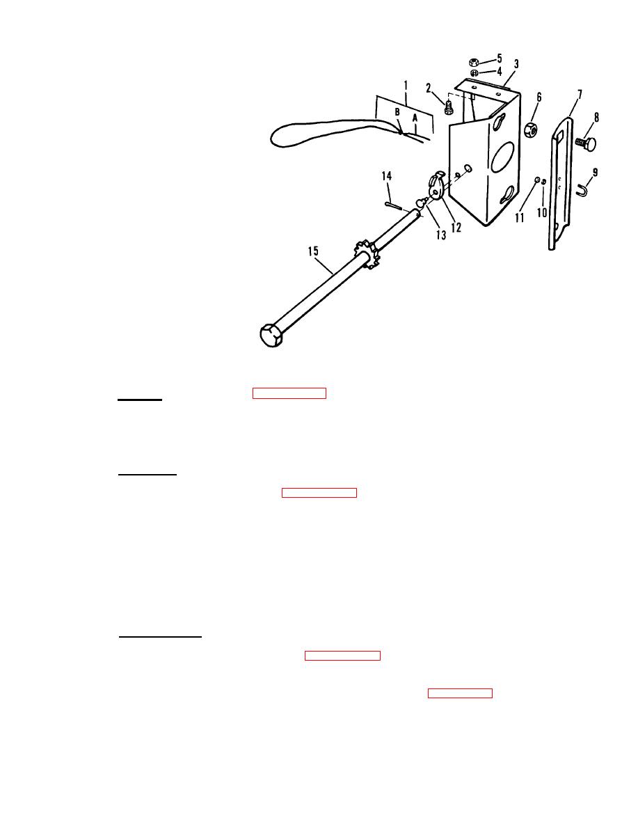
C a b l e assembly
A. Cable
B. F e r r u l e
2.
Screw
3.
B r a c k e t assembly
4.
Lockwasher
5.
Hex nut
6.
Nut
7.
W h e e l support
Square neck bolt
8.
9.
U-bolt
10.
Lockwasher
11.
Hex nut
12.
Pawl
13.
Rivet
14.
Cotter pin
15.
Operating shaft
S p a r e tire carrier, exploded view
e. R e p a i r . R e p l a c e c a b l e ( p a r a . 4 - 4 6 ) i f t h e r e a r e a n y b r o k e n s t r a n d s .
Tighten
u - b o l t i f l o o s e . B r a c k e t assembly can be reshaped if bent, but should be replaced
If ratchet on operating shaft
if it cannot be returned to proper working condition.
is broken or damaged, replace operating shaft.
If shaft pawl does not swing freely,
Replace any bolts or nuts that have seriously damaged threads.
replace pawl.
Assembly.
f.
(1) P o s i t i o n s h a f t p a w l ( 1 2 ,
figure 4-41) on bracket assembly (3) and secure
with rivet (13).
(2)
Insert operating shaft (15) through bracket assembly (3) and secure with
cotter pin (14).
( 3 ) R e p l a c e cable assembly ( 1 ) i n o p e r a t i n g s h a f t ( 1 5 ) a n d s e c u r e t o w h e e l
s u p p o r t ( 7 ) w i t h u - b o l t (9), lockwashers (10) and hex nuts (11).
(4)
Install two square neck bolts (8) and safety nuts (6) on wheel support (7).
Installation.
g.
( 1 ) Attach bracket assembly ( 3 , f i g u r e 4 - 4 1 ) t o r i g h t f r a m e r a i l w i t h s i x
screws (2), lockwashers (4) and hex nuts (5).
(2) Install spare tire and raise to carry position (para. 2-8).
4-73

