
TM 9-2330-388-14
4-47.
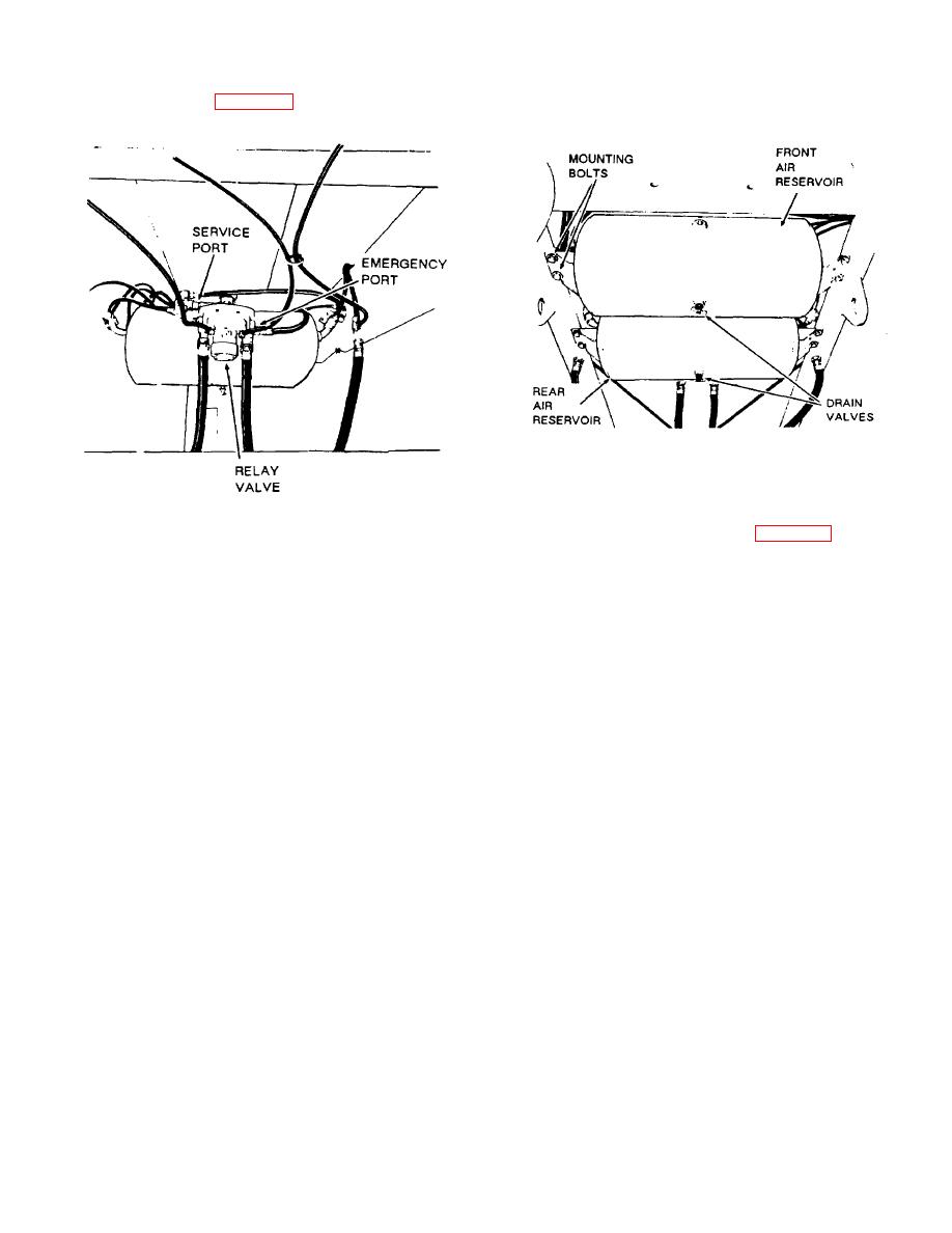
Air Reservoirs, Fig. 4-54.
Figure 4-54. Air Reservoirs.
replacing reservoir on frame. Close air drain valves.
Refill with air and check reservoir for leaks.
Figure 4-53. Emergency Relay valve Installation
4-48.
Pressure Protection Valve (Fig. 4-55.)
a.
Removal.
a.
Test and Adjustment.
(1) Block
semitrailer
wheels
to
prevent
(1) Attach air system test gage to trailer
movement.
"Emergency" gladhand with gage closest to trailer.
(2) Drain air from reservoir by opening drain
(2) Attach air supply line to valve end of test
valves on bottom of both air reservoirs.
gage. Air supply can be either a tractor or stationary
source.
(3) If air drain valves are to be replaced,
unscrew and replace with new ones.
(3) Pressurize system. Close valve on test
gage when system is full. Note gage reading. Drain
(4) If rear reservoir is to be replaced,
secondary (forward) air reservoir by opening drain valve
disconnect hoses and fittings to emergency relay valve.
(in bottom of reservoir. When all air has exhausted from
Relay mounted to a nipple on rear reservoir.
secondary system, gage should read 75 psi. If pressure
is not correct, adjust pressure protection valve as
(5) Remove air fittings on each end
of
follows:
reservoir. Remove two mounting bolts on each end
of
reserve and remove reservoir. If rear reservoir
is
(a) Loosen locknut (4) at base of cap.
remove emergency relay valve will be removed with
it.
Remove relay valve by unscrewing from nipple.
(b) Turn cap (5) clockwise to increase
pressure setting.
b.
Installation
(c) Turn
cap
counterclockwise
to
(1) Install new reservoir, bolt in place and
decrease setting.
reconnect fittings. If rear reservoir was replaced, screw
emergency relay valve onto reservoir nipple before
(4) Repeat step (3) until desired pressure is
obtained, then tighten lock nut.
(5) Remove air system test gage.
4-117
