
TM 9-2590-209-14&P
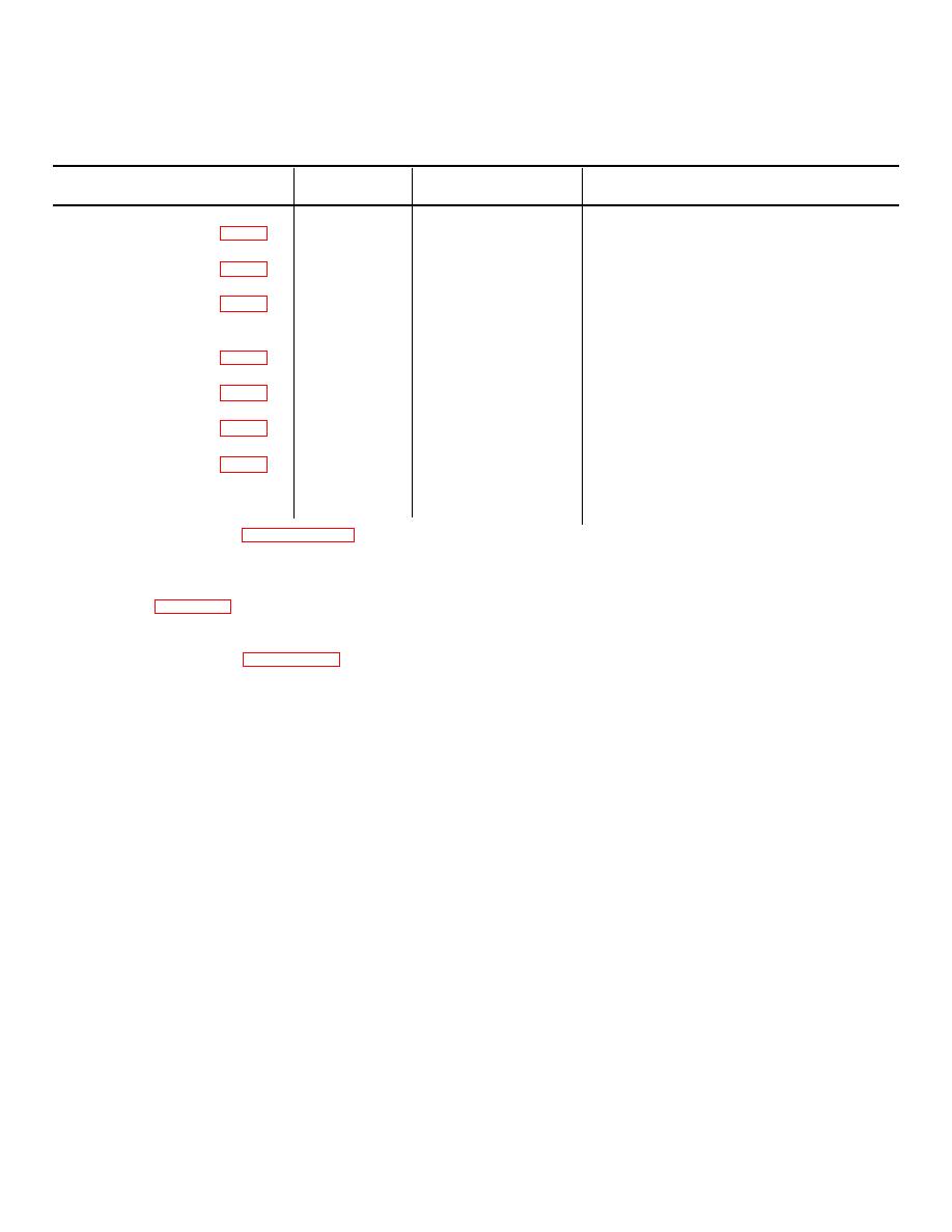
Table 10-6. Repair Standards for Blade Assembly
Cylinder and Ram
Fig.
Ref.
Point of
No
Letter
Measurement
Wear Limits
A
OD of piston
6.9740
B
ID of cylinder bore
7.021
C
ID of packing
2.507
retainer
D
OD of piston rod
2.497
E
ID of ram head bore
2.375 to 2.376
F
OD of bushing
2.377 to 3.379
G
ID of bushing
2.006
c. Cleaning. Refer to paragraph 5-5 for cleaning
(7) Slide piston rod (18) into head (11) bore.
instructions.
d. Inspection. Check the components for wear limit
(8) Slide washer (9) over rod (18).
as specified in table 10-6.
(9) Install piston (8) on rod (18).
e. Assembly. For assembly of the blade assembly
(10) Install packing assembly (7) on piston (8).
cylinder and ram, refer to figure 10-25 and proceed as
follows:
(11) Install preformed packing (5) on piston (6).
Install piston (6) on rod (18) to mate with packing set (7).
(1) During assembly, replace preformed
packing, seals, and/or all worn or deformed parts with
(12) Install washer (4) and nut (3) on rod (18)
new parts.
and secure with cotter pin (2).
(2) Install two bushings (20) in head (19).
(13) Install preformed packing (10) in cylinder
(1).
(3) Connect threaded head (19) to rod (18).
(14) Slide piston assembly into cylinder (1).
(4) Install packing assembly (14) into internal
bore of head (11).
(15) Install eight washers and screws (12 and
13) to secure head (11) to cylinder (1).
(5) Using two screws (17), secure retainer
(15) to head (11).
(6) Install seal (16) in retainer (15).
10-49
